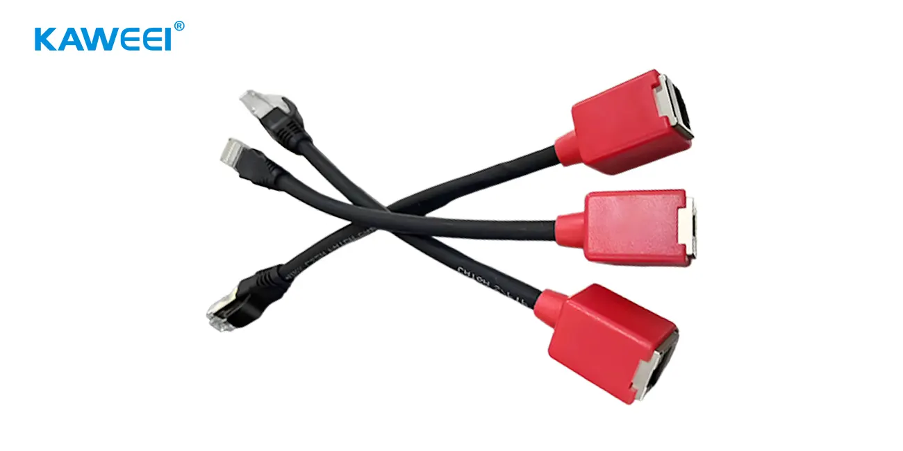
This article explains how an RJ45 Ethernet cable assembly is built and checked before it ships. The reliability of such an assembly depends on how well the cable and connector are matched, how conductors are terminated, how shielding is handled, and whether the finished part is tested against its target transmission category.
RJ45 vs. 8P8C: A Quick Clarification
8P8C describes a modular connector format with eight positions and eight contacts. RJ45 is commonly used as a trade term for the modular connectors found on Ethernet cables, although the terms are not technically identical in every context. Neither the connector's appearance nor its pin count establishes the cable assembly's Ethernet category or transmission performance.
Ethernet cabling categories have different electrical performance requirements and component specifications. For common RJ45-style assemblies, the cable, plug, termination process, and intended category must be compatible. Higher-category or application-specific designs should be checked against the relevant cabling standard and connector requirements rather than selected by connector appearance alone.
Cable and Connector Construction
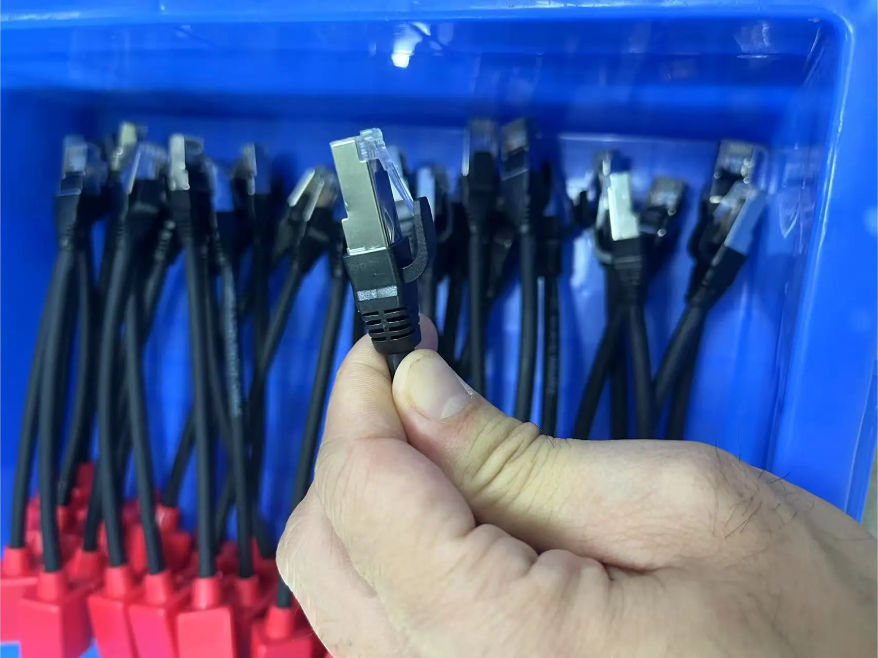
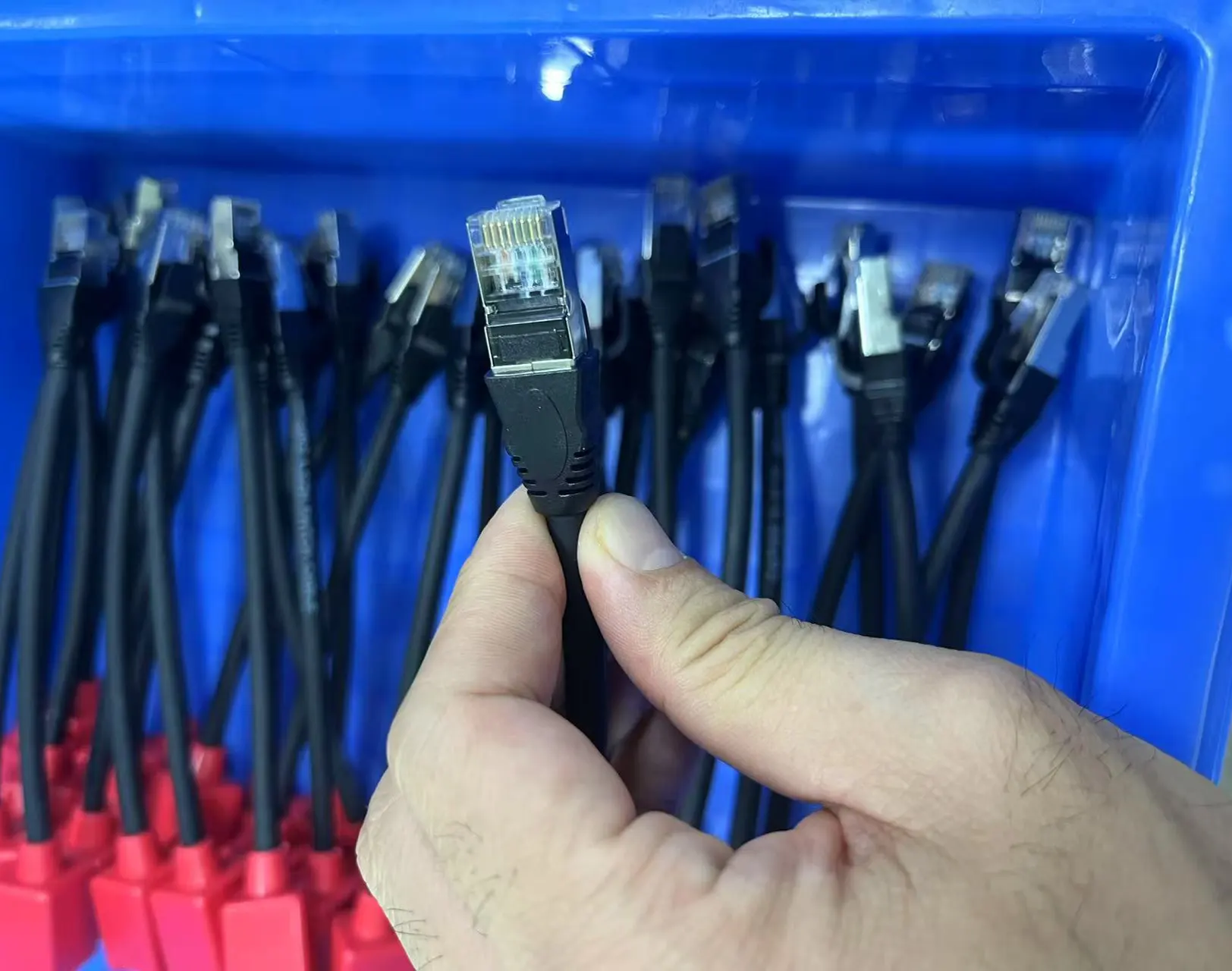
An RJ45 Ethernet cable assembly combines an 8P8C plug, a twisted-pair cable, and a connector overmold that protects the termination area.
The plug uses a standard eight-pin modular structure. For the connector body itself, many assemblies use a two-stage overmold: an inner mold and an outer mold. When a specific product is built this way, the inner mold material is selected for the connector geometry, the required flexibility, and the molding conditions of that design, rather than chosen as a universal rule. The outer mold provides a smooth transition between the connector and the cable jacket. A molded female assembly, where used, is described from its own drawing rather than assumed to be identical to the plug side.
A shielded Cat6A assembly may use S/FTP cable. In this construction, each twisted pair has an individual foil shield, while an overall braided shield surrounds the four pairs. Other cable constructions may be used where they meet the applicable electrical and installation requirements. A drain wire is included only when specified by the cable design. Conductors are often high-purity oxygen-free copper, and the jacket may be low-smoke, halogen-free (LSZH) material.
Low-smoke, halogen-free (LSZH) describes the material's low-smoke and low-halogen burning characteristics. It is a separate requirement from RoHS or REACH compliance. Whether a specific material or product meets RoHS or REACH should be confirmed through supplier documents, test reports, or declarations of conformity, and the applicable requirements depend on the target market and customer specification.
Shielding is designed to help control electromagnetic interference, but it is effective only when the shield path is properly terminated and connected to the mating system. High-frequency transmission performance is governed by conductor size, twist geometry, impedance consistency, return loss, crosstalk, and termination quality — not by conductor material alone.
Manufacturing Process
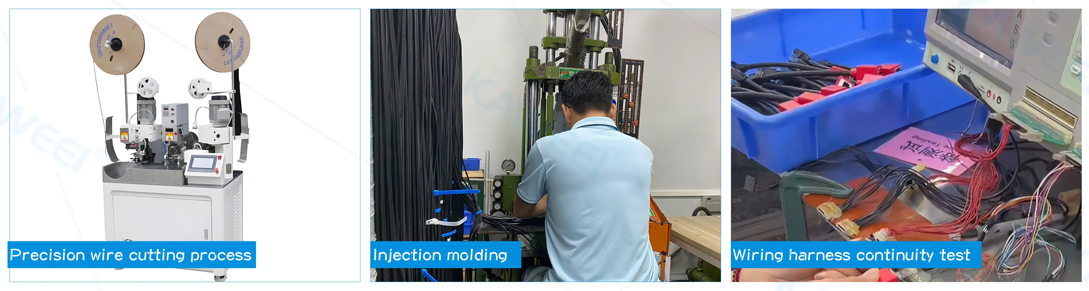
A typical manufacturing process includes the following steps. The exact operations and parameters follow the product drawing, the cable supplier's specification, and the applicable work instructions.
Cutting and Stripping
The cable is cut to the required length and the jacket is stripped to expose the twisted pairs and shield layers. The stripping process is controlled to minimize damage to the inner pairs, conductors, and shielding layers. Incoming cable is checked against the specification for construction, conductor size, and condition before it enters production.
Pair Arrangement and Connector Termination
Conductors are arranged and terminated according to the connector design and approved wiring diagram. For modular plugs, the conductor order and insertion depth must follow the specified pinout and termination instructions, and the termination process must provide the required electrical contact and mechanical retention. For a typical straight-through assembly, both ends follow the same T568A or T568B wiring scheme; cross-over cables and device-specific pinouts are built to the applicable drawing or customer specification instead.
The physical connection between the conductor and the terminal is established by the termination process; the overmold that follows mainly provides insulation, protection, and strain relief rather than the electrical bond itself.
Shielding Treatment and Strain Relief
For shielded assemblies, the shield layers are terminated according to the cable and connector design. Where a drain wire is provided, its termination follows the applicable drawing or work instruction. The process should preserve the intended shielding path, while overall shielding performance also depends on the mating interface, equipment design, and installation.
Strain relief is designed around the cable's expected bending, pulling, and environmental conditions. The overmold shape and materials are chosen to reduce stress concentration where the connector meets the cable.
Overmolding
Where a two-stage overmold is specified, the inner mold is formed around the termination area, and the outer mold completes the connector body and the transition to the cable jacket. Mold positioning is verified so that the connector and cable join smoothly and without exposed conductor or damaged shield. After molding, the assembly is inspected for incomplete coverage, visible voids or surface defects, flash, and other defects defined by the inspection criteria. Internal defects are evaluated using an appropriate inspection method where required by the product specification.
Finished Inspection and Testing
Finished RJ45 cable assemblies are inspected and tested according to the product specification, target performance category, connector design, and applicable requirements. Depending on the application, checks may include:
-
Wire-map testing — verifies conductor continuity, pair assignment, and pin mapping, identifying opens, shorts, reversals, and other wiring errors.
-
Insulation and dielectric testing — insulation resistance and dielectric withstand tests are performed when required by the product specification and applicable procedures.
-
Transmission performance testing — where category-level performance must be verified, relevant parameters may include insertion loss, return loss, and near-end crosstalk (NEXT), along with other applicable measurements.
-
Visual and mechanical inspection — checks connector condition, termination quality, shield termination, cable jacket integrity, and molding defects.
Test methods and acceptance limits must be defined for the specific assembly. A wire-map test verifies wiring integrity but does not establish compliance with a cable category or prove that an installed Ethernet link meets its performance requirements. Test records are maintained according to the applicable quality and traceability requirements.
Applications
RJ45 Ethernet cable assemblies are used wherever Ethernet connectivity is required. Typical applications include:
-
Data centers — interconnection between servers, switches, and storage devices on gigabit and 10-gigabit links.
-
Industrial control — network connections for PLCs, industrial routers, and similar equipment in electrically noisy environments.
-
Security monitoring — connections between cameras and network video recorders.
-
Commercial equipment — network connections for POS terminals and other smart devices.
Actual link performance depends on the cable assembly, network equipment, installation conditions, and applicable cabling requirements. Verifying an individual assembly does not automatically establish compliance of the complete installed channel.
Frequently Asked Questions
What is the difference between RJ45 and 8P8C?
8P8C describes a modular connector format with eight positions and eight contacts. RJ45 is commonly used as a trade term for the modular connectors found on Ethernet cables, although the terms are not technically identical in every context. Connector appearance alone does not establish Ethernet category compliance.
What should be checked when selecting an RJ45 cable assembly for 10 Gigabit Ethernet?
Check that the cable, connectors, and termination are matched to the target category and that the assembly has verified transmission performance for the intended link. The full installed channel must also meet the applicable cabling and installation requirements for the intended data rate.
What is the difference between shielded and unshielded RJ45 cable assemblies?
Shielded assemblies use conductive shielding structures designed to help control electromagnetic interference when properly terminated and integrated into the system. Unshielded assemblies do not use those cable or connector shielding structures. The appropriate design depends on the electrical environment, equipment interfaces, and installation requirements.
What is the difference between T568A and T568B wiring?
T568A and T568B define different conductor-to-pin assignments for common balanced twisted-pair Ethernet cabling. For a typical straight-through assembly, both ends use the same wiring scheme. Other pinouts should follow the applicable drawing or customer specification.
Does a continuity test prove that an RJ45 cable meets Cat6A requirements?
No. A continuity or wire-map test checks electrical connections and pin assignments, but it does not establish high-frequency transmission performance. The required transmission tests depend on the target category, assembly type, and applicable specification.
What information is needed to request a custom RJ45 cable assembly?
Provide the target cable category, cable length, connector types, shielded or unshielded construction, pinout, operating environment, required transmission performance, order quantity, and applicable compliance requirements. Drawings, samples, or existing part numbers can help clarify the design.
Requesting a Custom RJ45 Cable Assembly
Because cable construction, shielding, connector selection, and test requirements vary by application, most RJ45 Ethernet cable assemblies are built to specification. Contact our engineering team to discuss your requirements, request a quotation, or arrange sample evaluation.