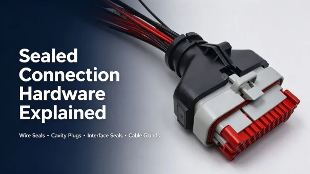
Waterproof connectors keep water out with a family of small elastomer sealing components working together — wire seals, cavity plugs, interface seals, O-rings, grommets, cable glands and gaskets. If any one of them is the wrong size, damaged or fitted incorrectly, the whole assembly can fail its IP rating even though every part looks normal.
This guide focuses on that sealing hardware itself — what each component does, where it sits, how it must be sized and why it fails. It is a deeper look than a general waterproof harness selection guide, and it assumes you already understand IP classes and connector families such as M8, M12, DT and MC4. If you need that foundation first, see our Waterproof Cable Assemblies Guide and Wire Harness Connector Selection.
What Makes a Harness Connector Waterproof?
A connector is waterproof only when its sealing system is complete, assembled correctly and used within its rated mating conditions. Three conditions all have to hold at the same time:
- A complete sealing system. Every possible water path — the wire entry, the mating interface, unused cavities and the cable exit — must have a seal in place. A single unsealed path defeats all the others.
- Correct assembly. Seals must be seated, not twisted or pinched; terminals must be fully inserted so their wire seals sit in the right groove; empty cavities must carry cavity plugs.
- Specified conditions. A connector's stated IP rating applies only under the conditions defined by its manufacturer, which may include a particular mating configuration, approved wire sizes, seals, protective caps and installation requirements. A high IP number never replaces correct hardware and workmanship.
Keep this system view in mind: when you troubleshoot a connector that "should be waterproof," you are almost always hunting for the one sealing component that is missing, mis-sized or misplaced.
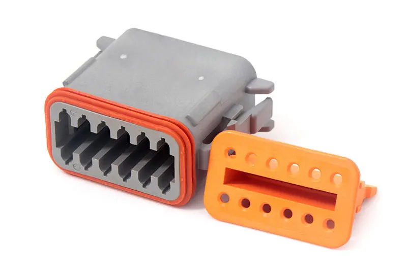
The Main Sealing Components in Waterproof Connectors
Waterproof connectors use a small set of standard sealing parts. Each one seals a different physical location. The table below summarises the five functional groups.
|
Component
|
What it seals
|
How it works
|
Typical material (examples)
|
|---|---|---|---|
|
Wire seal
|
The gap between each wire's insulation and the cavity wall
|
Compresses around the insulation OD; one seal per populated cavity
|
Silicone, EPDM, TPE
|
|
Cavity plug (blind seal)
|
Unused terminal cavities
|
Solid plug blocks the empty cavity so water cannot pass through
|
Silicone, EPDM
|
|
Interface seal
|
The mating face between plug and receptacle
|
O-ring in a gland or a flat face seal, compressed when halves mate
|
Silicone, NBR, FKM
|
|
Grommet / cable gland
|
The cable exit or enclosure entry
|
Covers the bundle at the rear; gland clamps the cable where it leaves the housing
|
Silicone, EPDM, TPU
|
|
Gasket / backshell seal
|
Panel-mount face and connector rear
|
Flat gasket under a panel flange; backshell seal at the connector back
|
EPDM, NBR, FKM
|
The material names in the table are examples only, not a universal pairing standard — verify every choice against the manufacturer's specification. The right elastomer for a given connector depends on operating temperature, fluid and chemical compatibility, compression set over life, and the manufacturer's design intent. Confirm the seal's temperature range and fluid compatibility against your application before specifying it.
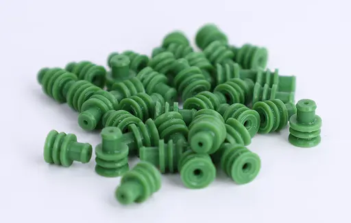
Wire Seals and Cable Sealing Grommets
A wire seal is a small elastomer ring that fits inside a terminal cavity and compresses around the wire's insulation. Its job is to seal the only path through the cavity wall — the hole the wire passes through. It must match the insulation outer diameter (OD), not the conductor size. A wire seal rated for 1.8–2.4 mm insulation OD will not seal a 3.0 mm jacket, and an oversized seal will leave a gap.
Two details matter most:
- Compression fit. The seal must be squeezed by a defined amount between the insulation and the cavity wall. Too little compression leaks; too much can crush the insulation or make the wire hard to insert.
- Seal position. The wire seal has to sit in its locating groove so the mating terminal and the seal align. A seal pushed too deep or left proud of the cavity weakens the interface.
A grommet is a larger elastomer element that covers several wires where they leave the connector or pass through a panel. Note that not every grommet is a seal: some grommets are used mainly for cable protection or strain relief, while others are designed to be waterproof. Their actual sealing role depends on the specific design, so treat the grommet's sealing function as design-specific rather than assumed.
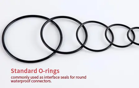
Connector Interface Seals and O-Rings
The interface seal closes the gap where the plug and receptacle halves meet. It is the seal people most often picture when they think of a waterproof connector. There are two common forms:
- O-ring in a gland groove. A torus-shaped ring seated in a groove on one half; when the halves mate, the mating surface compresses the ring and closes the interface.
- Flat face seal. A wide, flat elastomer gasket compressed between the two mating faces over the full mating footprint.
The interface seal is what keeps water from entering the mated connection itself. It must be compressed to a defined squeeze; too little lets water in at the parting line, and too much can extrude or over-stress the ring. Besides an O-ring and a flat face seal, some connectors use other specialised interface seals — for example a captive elastomer bead moulded into one housing half or a hybrid seal integrated with the locking feature. The specific form follows the connector design, so confirm the interface-seal arrangement for the series you use.
Cavity Plugs and Blind Seals
A cavity plug (also called a blind seal or sealing plug) fills an empty terminal cavity. Connectors are built with more cavities than a harness uses, so unused cavities are a direct water path unless they are plugged. The plug is usually the same material and shape as a wire seal but solid, so it blocks the cavity while pressing against the cavity wall.
For connectors designed to maintain sealing at unused terminal cavities, each unused cavity must be fitted with the specified cavity plug or sealing component, and you should always follow the connector manufacturer's cavity-sealing requirements. In such a design, a connector with an empty, unplugged cavity is not waterproof no matter how good its other seals are — this is one of the most common and most easily missed assembly errors. Not every connector uses the same cavity-sealing scheme, so confirm the requirement for your series.
Gaskets, Cable Glands, and Backshell Seals
These seal the outer boundaries of the connector system:
- Panel-mount gasket. A flat seal fitted under the flange of a bulkhead or panel-mount connector. It seals the face between the connector and the panel it passes through.
- Cable gland. A fitting that clamps down on the cable where it enters an enclosure or a sealed housing. It provides strain relief and seals the cable entry point.
- Backshell seal. A seal at the rear of the connector, protecting the point where wires transition into the back of the housing.
These parts matter whenever the connector is not a simple free-hanging pair — for example in a junction box, a bulkhead pass-through or a panel-mount application.
How Sealing Hardware Works Together
A waterproof connector typically has four sealing zones, and each zone must be closed for the assembly to hold its rating. The cross-section below shows where the sealing components sit in a representative plug-and-receptacle pair.
The cross-section reads left to right: each of the four zones — cable exit, wire entries, empty cavities and the mating interface — is closed by the component shown at that point. The connector's IP rating only holds when all four zones are sealed in the same assembly. If the diagram does not render in your publishing tool, the same information in text: at the cable exit a grommet or cable gland seals the bundle; at each wire entry a wire seal compresses around the insulation; at every unused cavity a cavity plug blocks the opening; and at the mating interface an O-ring or face seal closes the gap between the halves.
How to Match Seals to Wire and Connector Dimensions
Sealing depends on fit, and fit depends on dimensions. Three measurements drive nearly every sizing decision:
- Insulation OD of the wire. The wire seal must cover the actual measured insulation OD, including tolerance. Measure it, do not assume from the conductor gauge.
- Seal sealing range. Every wire seal specifies a range of insulation ODs it will seal — for example, one series might cover 1.4–2.0 mm depending on the connector series. The wire's insulation OD must fall inside that range with margin. Do not read the example figures as a universal or recommended range; always use the value from your connector's datasheet.
- Cavity and gland dimensions. The cavity bore, groove depth and gland opening determine how much the seal is compressed. Compression is normally expressed as a percentage of the seal's free cross-section, and the connector manufacturer specifies the acceptable range.
Follow the connector manufacturer's cavity and seal specification. If a seal is listed for a given wire range, use it within that range; do not substitute a visually similar seal from another series. Using the wrong seal is a leading cause of field failures, because the connector looks fully assembled yet leaks.
Example (hypothetical, for illustration only — not a universal design parameter): suppose a connector series lists a wire seal covering insulation OD 1.4–2.0 mm, and your cable measures 1.9 mm with a ±0.1 mm tolerance. Because the worst-case insulation OD reaches the upper limit of the stated sealing range, confirm that the full tolerance range is permitted by the connector manufacturer's specification. Do not assume acceptable sealing performance from nominal dimensions alone, and check the actual measured OD rather than the conductor gauge before assembling.
The checklist below summarises what to confirm before specifying or buying a seal for a waterproof connector.
|
Item to confirm
|
Why it matters
|
|---|---|
|
Connector series and cavity design
|
Confirms the seal is compatible with the connector structure
|
|
Wire insulation OD and tolerance
|
Confirms the wire sits within the seal's stated sealing range
|
|
Operating temperature and fluid exposure
|
Confirms the elastomer material and its conditions of use are suitable
|
|
Mated or unmated condition in service
|
Confirms the protection requirement for the actual use state
|
|
Required IP rating and verification method
|
Confirms the design requirement and how it will be verified agree
|
Common Waterproof Connector Sealing Failures
Most sealing failures come from a small set of avoidable causes:
- Mis-sized seal. A wire seal whose range does not cover the actual insulation OD, or an interface seal with too little compression. Result: water path remains even when all parts look fitted. Check: measure insulation OD against the seal range; confirm compression against the datasheet.
- Damaged seal. Nicks, cuts, flattened edges or hardened/aged elastomer. Damaged seals lose their squeeze and leak under pressure.
- Twisted or rolled seal. A wire seal rotated in its groove during wire insertion no longer seals around the full circumference.
- Terminal not fully inserted. If the terminal is not seated, its wire seal does not reach the correct groove and the cavity is not sealed. Check: confirm terminal seating and secondary-lock engagement per the manufacturer's inspection method.
- Unplugged empty cavities. One unused cavity left open defeats the entire IP rating.
- Over-tightening. Over-compressing a gland or interface seal can extrude or tear the elastomer.
Because these failures are invisible from the outside, verification has to be deliberate rather than assumed. The table below maps the water path you observe to the components to check first.
|
Observed water path
|
Components to check first
|
|---|---|
|
Water tracking along a single wire
|
Wire insulation OD, wire seal size and condition, seal seating
|
|
Water entering at the mating face
|
Interface seal, mated condition and lock, mating-face damage
|
|
Water entering through an empty cavity
|
Cavity plug present, correct type, correctly seated
|
|
Water entering at a panel or enclosure opening
|
Panel gasket, cable gland, mounting hole and housing interface
|
How to Verify a Sealed Connector Assembly
Before an assembly can be trusted, it should pass three practical checks. These are not a substitute for the formal IP rating verification methods described in our waterproof cable assembly rating test guide, but they catch most assembly errors:
- Visual inspection. Check every wire seal for correct seating, no twist, no visible damage, and confirm every empty cavity has a cavity plug.
- Terminal seating check. Verify terminal seating and secondary-lock engagement using the connector manufacturer's specified inspection method. Where required, perform a terminal-retention test separately. Confirm seal position and condition through the prescribed visual or assembly inspection procedure.
- Sealing verification. Use the test method, setup and acceptance criteria specified by the applicable IP standard and the connector manufacturer's documentation. A leak or air-pressure test may be useful for process verification, but it does not automatically establish compliance with an IP rating.
The distinction matters: assembly verification proves the hardware was put together correctly; IP rating testing proves the design meets a stated level of protection. Both are needed, but they answer different questions. These standards are not interchangeable, and neither applies to every industrial waterproof connector: SAE/USCAR-2 (current revision 8) covers performance testing of low-voltage (0–20 V DC) automotive electrical connector systems; ISO 20653:2023 covers the IP-code protection of the enclosures of road-vehicle electrical equipment. Always pair them with the connector manufacturer's own product specification for the exact procedures and acceptance criteria that apply to your part.
FAQ
What is the difference between a wire seal and an interface seal?
A wire seal closes the gap between each individual wire's insulation and its cavity wall, so water cannot track along a wire into the connector. An interface seal closes the gap between the mating faces of the plug and receptacle, so water cannot cross the parting line between the two halves. They seal different physical locations and both are needed.
Do unused connector cavities need sealing plugs?
Yes, where the connector is designed to maintain sealing at unused terminal cavities. An unused, empty cavity is a direct water path into such a connector, so each empty cavity must be filled with the specified cavity plug (blind seal) to restore the seal. Leaving one open can defeat the connector's IP rating even when every other seal is correct. Follow the manufacturer's cavity-sealing requirements for your series.
Can a waterproof connector remain waterproof without its mating half?
Many sealed connectors achieve their specified ingress protection only when correctly mated. If protection is required while the connector is unmated, check whether the design provides an independent sealing mechanism or requires a rated protective cap.
Does a higher IP rating guarantee a better seal for every application?
Not by itself. A higher IP number means the connector meets a stricter ingress test under defined conditions, but real-world sealing still depends on correct hardware selection, correct wire-size matching, complete cavity sealing and careful assembly. Choosing a high IP connector does not compensate for a mis-sized or damaged seal.
For related guidance, see our Waterproof Cable Assemblies Guide, Wire Harness Connector Selection and IP Rating Verification Methods.