by Admin
2026-07-22 10:30:15
UL1007 Wire Harness Guide | UL758 Standards, AWG Selection & Custom Cable Assembly
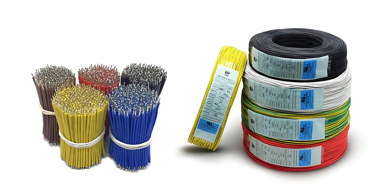
UL1007 wire is one of the most widely used electronic wires globally for internal wiring in industrial automation equipment, consumer electronics, medical instruments, smart home devices, and control systems. Thanks to its excellent processing characteristics, mature supply chain, and compliance with North American safety standards, UL1007 has become a standard choice for numerous equipment manufacturers and wire harness assembly plants.
However, in actual projects, simply selecting UL1007 is not sufficient to guarantee the reliability of the final wire harness.
When assisting clients with wire harness prototyping, we frequently encounter the following issues:
- What is the difference between UL1007 and UL1015?
- How should I choose between 24AWG and 26AWG?
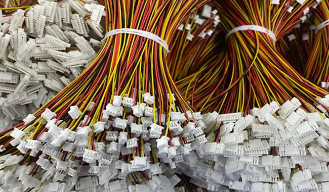
- Which JST, Molex, or TE connectors are suitable for UL1007?
- Why do terminal pull tests fail?
- How can I ensure the product meets safety requirements for the North American market?
These issues not only affect product performance but can also increase rework costs, extend project timelines, and even impact system-level certification.
Drawing on practical manufacturing experience, this article provides a comprehensive overview of UL1007 electronic wire harnesses, covering aspects such as engineering design, material selection, connector compatibility, crimping processes, quality control, and international standards. The aim is to help R&D engineers, procurement professionals, and equipment manufacturers develop a more holistic approach to component selection.
Note: The engineering experience discussed herein is primarily derived from in-house practices regarding wire harness development, prototyping, and mass production; it is intended solely as a reference for product design and manufacturing. Specific product designs must still be validated against actual application environments, customer drawings, and relevant standard requirements.
What is UL?
Many engineers new to export products often ask: What exactly is UL?
UL (Underwriters Laboratories) is an independent product safety certification organization founded in the United States, with a long history of involvement in safety testing and standards development for electrical products, electronic equipment, and components.
For equipment manufacturers, the significance of UL lies primarily in the following:
When products are exported to the U.S. or Canadian markets, the internal wiring used within the complete unit generally must comply with the relevant requirements for UL Appliance Wiring Material (AWM).
Among them, the most common standards are:
- UL758 — Appliance Wiring Material (AWM)
- UL1581 — Electrical Wire Test Methods
- UL2556 — Wire and Cable Test Methods (applicable to certain products)
It should be noted that UL1007 is not a certification in itself, but rather an AWM Style (wire specification) within the UL758 standard.
In other words, when a wire is described as "UL1007 wire," it typically means it is manufactured in accordance with the technical requirements of Style 1007 under the UL758 standard; it does not imply that every UL1007 wire automatically holds an independent product certification. Therefore, when sourcing, it is advisable to verify that the wire is supplied by a manufacturer holding valid UL recognition.
What is UL1007 wire?
UL1007 is a PVC-insulated single-core hook-up wire primarily used for fixed internal wiring in equipment.
Thanks to its ease of processing, moderate cost, and wide range of color specifications, it has become one of the most common standard wire types in the wire harness industry.
Typical technical parameters are as follows:
| project | UL1007 |
| standard | UL758 AWM Style 1007 |
| Rated voltage | 300V |
| Standard operating temperature | 80°C |
| Insulating materials | PVC |
| conductor | Bare or tinned stranded copper wire |
| Flame-retardant properties | VW-1 (depending on wire specifications) |
| Applications | Equipment Internal Wiring |
In wire harness manufacturing, we generally recommend using tinned copper conductors; compared to bare copper, tinned copper offers the following advantages:
- Superior oxidation resistance;
- Better suited for long-term storage;
- Higher crimping consistency;
- More stable welding performance;
- Greater reliability in humid environments.
Of course, for different application scenarios, the appropriate conductor material should still be selected based on product requirements, rather than simply assuming that tinned copper is inherently superior to bare copper.
Why is UL1007 so well-suited for wire harness manufacturing?
For wire harness manufacturers, the ease of mass-producing a specific type of wire is often more important than its technical specifications alone.
UL1007 has become one of the most widely used electronic wires in the industry primarily for the following reasons:
1. Stable processing performance
The PVC insulation layer offers excellent flexibility and processing characteristics.
When processed on automatic wire-cutting machines, UL1007 maintains consistent stripping lengths and insulation integrity, thereby reducing the number of defective parts caused by insulation damage.
2. High compatibility with mainstream connectors
UL1007 is compatible with a wide range of standard connector systems, such as:
- JST
- Molex
- TE Connectivity
- XH
- PH
- ZH
- VH
- SM
Therefore, wire harness design can be rapidly completed for both industrial control equipment and consumer electronics.
3. Extensive range of AWG sizes
UL1007 is available in a wide range of sizes, from fine gauge to larger gauge, including:
- 30AWG
- 28AWG
- 26AWG
- 24AWG
- 22AWG
- 20AWG
- 18AWG
Different wire gauges accommodate signal transmission, power supply, and internal equipment space constraints, offering significant flexibility in engineering design.
4. Mature global supply chain
As UL1007 has been widely used for many years, most wire harness manufacturers have established mature raw material inventories and processing techniques.
This not only helps shorten sample lead times but also ensures consistent product quality and effective cost control during mass production.
What are the differences between UL1007, UL1015, and UL1571?
When submitting inquiries for wire harnesses, many customers simply specify "UL electronic wire" without indicating a specific model. In reality, while UL1007, UL1015, and UL1571 all belong to the UL758 Appliance Wiring Material (AWM) series, there are significant differences among them regarding voltage ratings, temperature ratings, insulation thickness, and application scenarios.
Improper selection can result in an excessively large wire harness outer diameter, insufficient flexibility, or a failure to meet the equipment's operating environment requirements. Therefore, clearly defining wire specifications during the initial project phase helps reduce the cost of subsequent modifications.
Comparison of UL1007, UL1015, and UL1571
| project | UL1007 | UL1015 | UL1571 |
| standard | UL758 AWM Style 1007 | UL758 AWM Style 1015 | UL758 AWM Style 1571 |
| Rated voltage | 300V | 600V | 30V |
| Rated temperature | 80°C | 105°C | 80°C |
| Insulating materials | PVC | PVC | Ultra-thin PVC |
| Insulation thickness | medium | Relatively thick | Ultra-thin |
| Finished product outer diameter | Smaller | relatively large | Minimum |
| Flexibility | good | good | excellent |
| Common AWG sizes | 18–30AWG | 18–30AWG | 28–40AWG |
| Typical Applications | Internal equipment wiring | Power supply and high-temperature areas | LCDs, laptops, consumer electronics |
Looking at actual projects:
- UL1007 is better suited for the internal wiring of the vast majority of industrial equipment, home appliances, and automation control systems;
- UL1015 is commonly used for power supply lines requiring higher operating temperatures or higher voltage ratings;
- UL1571 is primarily applied in space-constrained electronic products, such as LCD monitors, printers, cameras, and laptops.
It should be noted that the above comparison serves only as a reference for common engineering selection; the final determination must be made by comprehensively considering product structure, current load, ambient temperature, and customer specifications.
Why do most wire harness projects choose UL1007?
In the daily production operations of wire harness factories, UL1007 typically accounts for a significant share of usage, and price is not the only reason for this.
1. Capable of meeting the internal wiring requirements of most devices.
For applications with a rated voltage not exceeding 300V and a continuous operating temperature no higher than 80°C, UL1007 typically meets design requirements while balancing cost and processing efficiency.
Typical applications include:
- PLC control cabinets
- Automation equipment
- Smart home controllers
- LED drivers
- Internal connections for medical instruments
- Industrial displays
- Control boards for small home appliances
2. Small outer diameter, facilitating internal equipment wiring.
Compared to the thicker insulation of UL1015, UL1007 effectively reduces the overall outer diameter of the wire harness while maintaining adequate mechanical strength.
This is particularly important for equipment requiring multi-core wiring or operating within limited installation space.
For instance, the interior of a controller unit might require dozens of wire harnesses of varying lengths. Using wires with thicker insulation for all of them would not only complicate assembly but could also compromise heat dissipation and the space available for maintenance.
3. Automated processing has matured.
UL1007 has been widely used for many years, and most automatic wire cutting, stripping, and crimping equipment can process it reliably.
For mass production, this means:
- More stable stripping dimensions
- Lower defect rate
- Higher production efficiency
- Easier to maintain batch consistency
How do you choose the right AWG?
AWG (American Wire Gauge) is a standard for wire sizes commonly used in North America.
It is important to note the following:
The higher the AWG number, the smaller the conductor diameter; the lower the AWG number, the thicker the conductor.
Many new engineers mistakenly believe that a higher number indicates a thicker wire; this is a common misconception.
Reference for Common UL1007 AWG Specifications
| AWG | Conductor diameter (approx.) | Recommended Current | Common Applications |
| 30AWG | 0.25 mm | ≤0.8A | PCB signal lines |
| 28AWG | 0.32 mm | ≤1.4A | Communication signal |
| 26AWG | 0.40 mm | ≤2.2A | Sensors, control lines |
| 24AWG | 0.51 mm | ≤3.5A | Industrial control equipment |
| 22AWG | 0.64 mm | ≤5A | Control system, power cord |
| 20AWG | 0.81 mm | ≤8A | Low- to medium-power supply |
| 18AWG | 1.02 mm | ≤10A | Motors, power supply modules |
Note: The current data above serve as reference values based on common engineering practice. Actual current-carrying capacity is influenced by factors such as conductor length, ambient temperature, installation method, wire harness density, and equipment specifications; therefore, assessments should be based on actual operating conditions during the design process.
How do engineers select the AWG?
In practical design, we typically do not select the wire gauge based solely on current; instead, we consider several factors comprehensively.
1. Operating current
This is the most fundamental consideration.
Higher currents generally require thicker conductors to reduce voltage drop and heat generation.
For example:
- 28AWG or 26AWG wire may be used for button signal lines;
- 24AWG is commonly used for PLC I/O control lines;
- 22AWG or 20AWG may be selected for power supply lines.
2. Wire length
The longer the conductor, the higher the resistance.
If the internal wiring of the equipment is long, it may be necessary to increase the conductor's cross-sectional area—even if the current is low—to minimize voltage drop.
3. Installation Space
For compact devices—such as medical instruments, consumer electronics, or industrial displays—thinner wires can reduce wire harness volume and improve assembly efficiency.
However, excessively reducing the wire gauge can compromise mechanical strength, so a balance must be struck between space constraints and reliability.
4. Mating Connector Specifications
Connector terminals typically have a corresponding applicable AWG range. For example:
| Connector Series | Commonly applicable AWG sizes |
| JST SH | 28–32AWG |
| JST ZH | 26–30AWG |
| JST PH | 24–28 AWG |
| JST XH | 22–26AWG |
| JST VH | 18–22AWG |
| Molex Mini-Fit | 18–24AWG |
If the wire specifications fall outside the terminal's design range, even if crimping is possible, the contact reliability or tensile strength may be compromised.
Common Application Scenarios for UL1007
Based on the projects we have encountered, UL1007 is commonly found in the following equipment:
Industrial Automation
- PLC Control Cabinet
- Industrial Robot
- Servo Drive
- HMI (Human-Machine Interface)
- Industrial Sensor
Features:
- Typically utilizes 24AWG and 22AWG wire;
- Compatible with connectors from JST, Molex, TE, etc.;
- Focuses on long-term operational stability.
Medical equipment
For example:
- Testing Instruments
- Ultrasound Equipment
- Medical Display Terminals
- Laboratory Equipment
Medical equipment typically places greater emphasis on:
- Conductor consistency;
- Traceability;
- Assembly precision;
- Long-term reliability.
For certain medical projects, it may also be necessary to select materials that meet specific environmental or regulatory requirements, in accordance with client specifications.
Smart home systems include:
- Smart Door Locks
- Security Controllers
- Smart Lighting
- Climate Control Devices
These products are typically produced in large volumes; therefore, in addition to performance, manufacturing efficiency and cost control are also important considerations.
Consumer electronics, such as:
- Audio equipment;
- Monitors;
- Gaming equipment;
- Small home appliances.
In products with limited space, designers may sometimes select wires with finer gauges or other AWM styles based on structural requirements, to balance assembly space constraints with electrical performance.
Recommendations for Engineering Practice
During our wire harness development process, if the customer has not yet specified the wire specifications, our engineering team typically conducts a preliminary assessment based on factors such as rated current, operating temperature, installation space, connector compatibility, and target market regulations before confirming the final solution with the customer.
Although this initial consultation adds a small amount of design time, it often reduces the risk of subsequent sample modifications and rework during mass production, ultimately helping to improve overall project development efficiency.
From blueprints to finished product: How is a UL1007 wire harness manufactured?
Many clients assume that a wire harness is simply a matter of connecting a few wires. In reality, however, a seemingly simple UL1007 wire harness typically involves multiple manufacturing steps, with every stage impacting the product's electrical performance, mechanical strength, and long-term reliability.
For mass-production projects, the manufacturing process generally includes:
- Engineering drawing review
- Raw material verification (wire, connectors, terminals)
- Prototype production
- Automatic wire cutting and stripping
- Terminal crimping
- Housing assembly
- Post-processing (heat-shrink tubing, braided sleeving, cable ties, etc.)
- 100% continuity testing
- Visual inspection and packaging for shipment
Before full-scale production, we typically complete sample validation and confirm key dimensions, connector models, wire colors, and assembly orientation with the customer to minimize the risk of rework during mass production.
Step 1: Confirm drawings and BOM.
Whether for OEM or ODM projects, the engineering review is a crucial step before production begins.
The engineering team typically needs to confirm the following:
Wire specifications, for example:
- UL1007
- 24AWG
- Black
- Tinned Copper
This information determines the wire size, crimping parameters, and subsequent processing methods.
Length requirements—confirmation needed:
- Total length
- Stripping length
- Whether both ends are identical
- Whether tolerances are allowed
For example:
- Overall Length:300 ±2 mm
- Left Strip:3 mm
- Right Strip:5 mm
Different products may have varying requirements for length tolerances; therefore, these should be confirmed with the customer during the sampling stage.
Connector model examples:
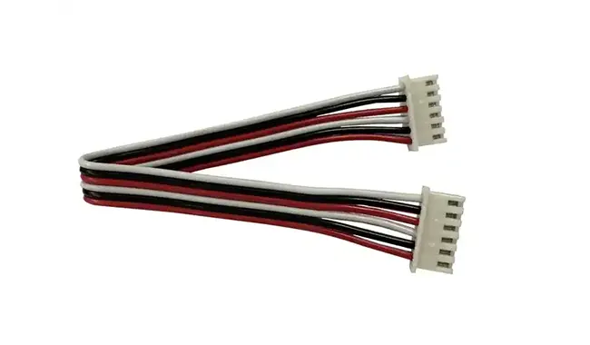
- JST XH2.54
- JST PH2.0
- Molex KK
- TE Micro Match
Engineers need to confirm not only the plastic housing model but also:
- Number of pins
- Latch orientation
- Polarity
- Pin arrangement
Many cases requiring rework are not due to incorrect wiring, but rather because the connector was installed with the wrong orientation.
Pin assignment example:
| Pin | Color |
| 1 | Red |
| 2 | Black |
| 3 | Yellow |
| 4 | White |
Although an incorrect color sequence does not affect electrical continuity, it can prevent the device from being installed correctly; therefore, it is generally classified as a serious assembly defect.
Step 2: UL1007 Wire Processing
Once the drawings are confirmed, the wire processing stage begins. Modern wire harness factories typically employ fully automated wire cutting and stripping equipment. The main process steps include:
- Automatic feeding
- Fixed-length cutting
- End stripping
- Length detection
Compared to manual processing, automated equipment can improve consistency and reduce human error.
However, even when using automated equipment, the dimensions of the first article still require verification.
Typically, the following need to be checked:
- Total length
- Stripping length
- Whether copper strands are nicked/cut
- Whether PVC insulation is damaged
If significant indentations or broken copper strands are observed in the insulation layer, the blade depth should be readjusted rather than continuing production.
Step 3: Terminal Crimp — A critical process determining wire harness reliability.
Many customers believe that as long as the terminal is securely crimped, that is sufficient. In reality, terminal crimping is one of the most critical processes in wire harness manufacturing. The long-term, stable performance of a wire harness depends largely on the quality of the crimp.
Typical crimping areas include:
- Conductor Crimp Area
- Insulation Crimp Area
Ideally:
The conductor crimp ensures stable electrical conductivity;
The insulation crimp secures the wire, reducing the direct tensile force exerted on the copper strands.
Any abnormality in either of these areas could affect the product's service life.
Why can't a "universal mold" be used?
Many new customers ask:
"Can a single die crimp all types of terminals?"
The answer is usually no.
The reason is simple:
Terminals from different brands and series differ in dimensions and structure.
For example:
- JST PH
- JST XH
- Molex KK
- TE Connectivity
Although they look similar, their crimp dimensions are not identical.
Using mismatched molds makes it prone to: Loose crimp connection
- Over-tightened crimp connection
- Exposed copper strands
- Cracked terminal
- Increased contact resistance
Therefore, for mass production, specific crimping dies are typically prepared for different terminals, and the crimp height is adjusted according to the wire's AWG.
Engineering Experience Sharing: Crimp Parameters Must Be Re-verified After Changing AWG
During the wire harness development process, we encountered a situation similar to the following:
An industrial control project initially utilized 26AWG UL1007 tinned copper wire. While the samples functioned correctly during initial testing, some failed to meet performance targets during internal tensile strength validation.
The engineering team subsequently re-evaluated the wire specifications, terminal model, and crimp height, adjusting the design to 24AWG UL1007 and optimizing the crimping parameters.
Upon re-validation, both conductor retention and crimp consistency showed improvement; consequently, the revised design was adopted for subsequent production.
It should be noted that:
The case study above reflects only the internal process validation; it does not imply that all 26AWG wires will exhibit similar issues. Actual component selection should be based on a comprehensive assessment of terminal specifications, customer drawings, performance requirements, and applicable standards.
This process of validation and optimization during the sampling stage is a common practice in the development of many wire harness projects.
Step 4: Connector Assembly
Once crimping is complete, the plastic housing can be assembled.
Although the process appears simple, there are actually several details that require attention. For example:
- Is the pin sequence correct?
- Is the orientation of the locking mechanism consistent?
- Are the terminals fully locked in place?
- Is there any terminal back-out?
Experienced operators typically perform a gentle pull test to confirm that the terminal has fully clicked into the locked position.
For certain high-pin-count connectors, auxiliary fixtures are also used for positioning to minimize assembly errors.
Step 5: Wire Harness Post-processing
Depending on the product's application environment, UL1007 wire harnesses can also incorporate various protective treatments. Common solutions include:
Heat Shrink Tubing: Primarily used for
- Reinforcing insulation;
- Securing branches;
- Improving appearance.
Braided Sleeve: Suitable for
- Industrial equipment;
- Automated machinery;
- Robotic wire harnesses.
Enhances abrasion resistance while keeping cable bundles neat and organized.
Corrugated Tube: Commonly found in
- Automotive wiring harnesses;
- Construction machinery;
- Outdoor equipment.
Its primary function is to provide additional mechanical protection.
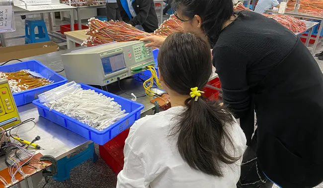
Step 6: 100% Electrical Testing
In mass production, manual visual inspection alone cannot guarantee that every wire harness meets the requirements.
Therefore, most projects include electrical testing for the finished products.
The testing typically covers:
- Continuity Test
- Open Circuit Test
- Short Circuit Test
- Pin Mapping Verification
For projects with special client requirements, the following may also be added:
- Dielectric Withstand Test (Hi-Pot)
- Insulation Resistance Test
- Contact Resistance Test
Specific test items and acceptance criteria shall be executed in accordance with the customer's technical specifications and product application requirements.
Why is sample verification more important than rework?
During the wire harness manufacturing process, we generally recommend that customers finalize sample approval before mass production begins.
The reason is simple:
It is typically less costly to identify issues and adjust designs during the sampling stage than to rework products in bulk.
Through sample validation, the engineering team can further confirm:
- Whether the wire specifications are appropriate;
- Whether the connector selection is correct;
- Whether the terminal crimping is secure;
- Whether the assembly space meets requirements;
- Whether subsequent mass production is repeatable.
For projects requiring long-term supply, this preliminary validation process typically enhances product consistency and reduces risks associated with subsequent production.
Quality Control Throughout Manufacturing
To ensure the consistency of UL1007 wire harnesses, established manufacturing plants typically implement quality control throughout the entire production process, rather than relying solely on pre-shipment inspections.
Typical processes include:
- Incoming Material Inspection
- First Article Inspection
- In-process Inspection
- Final Inspection
For raw materials, the primary checks involve verifying that wire specifications, AWG, connectors, terminals, and colors comply with BOM requirements; for first-article samples, the focus is on inspecting length, stripping dimensions, pin assignments, and assembly orientation to ensure any issues are identified before mass production.
Crimp Quality Verification
The quality of terminal crimping directly affects the mechanical strength and electrical reliability of the wire harness.
During the wire harness development process, verification typically incorporates the following aspects:
- Pull Force Test: Verifies that terminal retention force meets requirements;
- Crimp Cross-Section Analysis: Examines the compression state of the conductor and checks for anomalies such as broken strands or voids;
- Continuity Test: Verifies electrical continuity, pin mapping, and checks for short circuits;
- Visual Inspection: Checks connector orientation, terminal locking, wire color, and visual quality.
Test items and acceptance criteria may vary depending on the customer; final execution should be based on product specifications.
Common Standards for UL1007 Wire Harnesses
The following international standards are frequently referenced during the design and manufacturing of wire harnesses:
| Standard | Purpose |
| UL758 | Appliance Wiring Material (AWM) Wire Specification |
| UL1581 | Electrical and Flame-Retardant Test Methods for Conductors |
| IPC/WHMA-A-620 | Acceptance Standards for Wire Harness Crimping, Soldering, and Appearance |
| RoHS | Requirements for the Restriction of Hazardous Substances |
| REACH | EU Chemicals Regulation |
Not all of these standards necessarily apply to every project simultaneously; however, they frequently serve as important references for customer procurement specifications when exporting to North American or European markets.
Engineering Validation
During the wire harness prototyping phase, the engineering team typically conducts internal validation regarding various wire gauges, terminal combinations, and crimping parameters—such as comparing crimping results across different AWG sizes, optimizing crimp heights, or evaluating different connector solutions.
These validation activities are primarily intended for process optimization and sample development and cannot replace final product certification. Final verification based on customer drawings, actual application environments, and relevant industry standards must still be completed before mass production.
Frequently Asked Questions
Q1: Can UL1007 be used outdoors?
Generally, it is not recommended. UL1007 is primarily intended for internal equipment wiring; outdoor environments typically require cables with superior UV and weather resistance.
Q2: How should I choose between UL1007 and UL1015?
Consider UL1015 if the equipment operates at higher temperatures or requires a 600V voltage rating; for the internal wiring of standard equipment, UL1007 is usually sufficient.
Q3: Which AWG sizes are commonly used for UL1007 wire?
24 AWG, 22 AWG, and 20 AWG are the most common specifications in industrial equipment; the specific choice should be based on a comprehensive assessment of current requirements, connectors, and installation space.
Q4: Which connectors are compatible with UL1007 wire?
Common brands include JST, Molex, and TE Connectivity, covering series such as XH, PH, ZH, VH, and SM; the final selection must match the specific terminals and AWG range.