By quanyu lee
2024-12-28 02:45:28
Knowledge sharing on how to deal with broken flexible flat cables
Flexible flat cables (FFCs) are widely used in consumer electronics, medical devices, automotive electronics, and industrial control systems due to their lightness, flexibility, and ease of wiring. However, FFCs often break during long-term use or during bending, disrupting the normal operation of devices. This article will comprehensively share methods for dealing with FFC breakage, including cause analysis, troubleshooting methods, repair steps, and preventative measures.
1. What is a flexible flat cable?
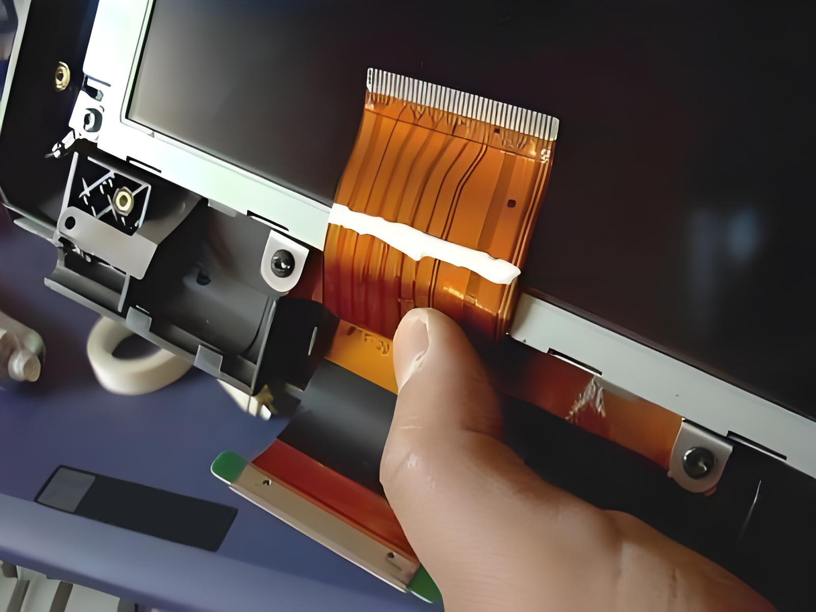
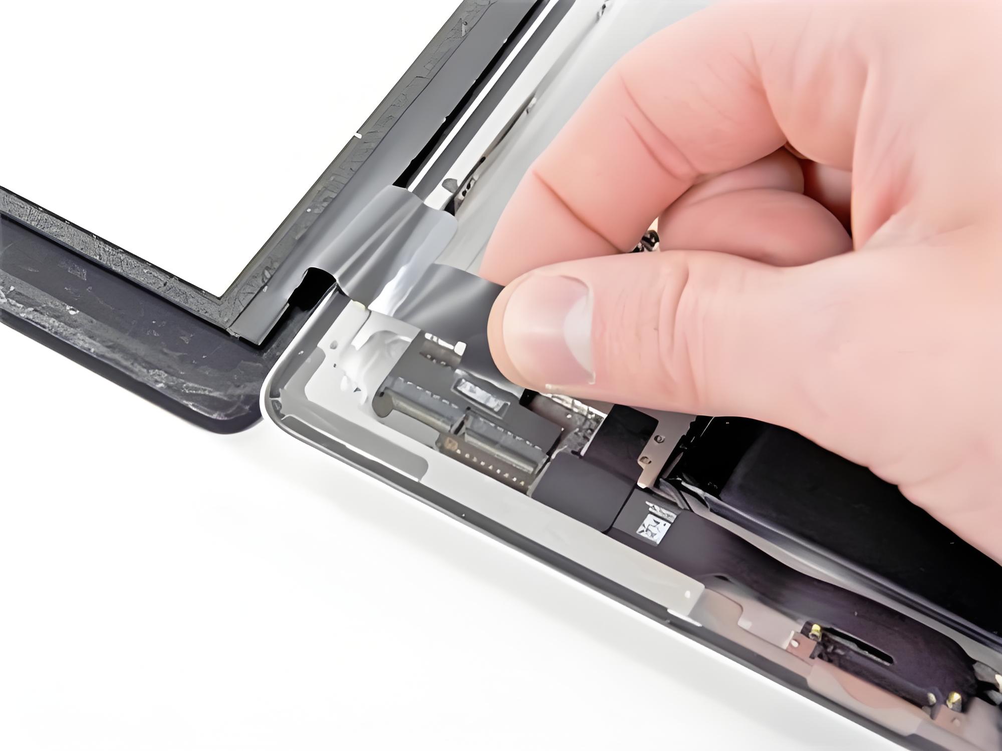
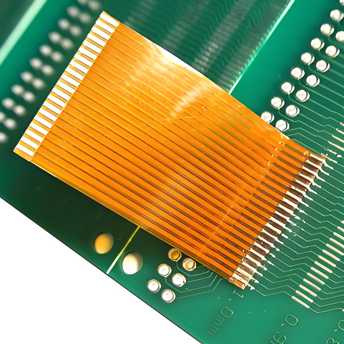
A flexible flat cable (FFC) is a cable consisting of multiple metal conductors arranged in parallel and covered with a flexible insulating material. It resembles a flat ribbon. Compared to traditional round cables, it offers advantages such as light weight, compact size, and a small bend radius. Therefore, it is widely used in precision electronic devices such as laptops, printers, LED displays, and camera modules.

2. Reasons Why Flexible Flat Cables Frequently Break
Frequent Bending: Prolonged bending at hinges (such as laptop hinges) can cause metal fatigue.
Improper Installation: Excessive stretching or bending at too shallow an angle can easily cause cracks in the internal conductors.
Environmental Impacts: High temperatures, humidity, or chemical corrosion can accelerate insulation degradation, leading to breakage.
Quality Issues: Cables made of inferior materials or poor workmanship can significantly reduce their durability.
3. Flexible Flat Cable Troubleshooting
Before repairing a cable, troubleshooting is essential:
Appearance Inspection: Observe the cable surface for creases, cracks, burn marks, or peeling.
Continuity Test: Use a multimeter to verify continuity between the two ends of the conductor to quickly identify any shorts.
Professional Support: For complex applications, Kaweei's wire harness customization facility offers professional testing and customization capabilities for accurate diagnosis and alternative solutions.
When selecting a cable, you should consider whether it complies with the UL standard (Underwriters Laboratories) certification.

4. Determine the break location of the flexible flat cable
Two practical methods offer efficient and effective methods for locating a broken flexible flat cable. The first involves segmented testing, which measures the resistance of the cable conductor section by section. By determining whether there are any anomalies (such as a sudden increase or infinite resistance), the fault's location is narrowed down, gradually pinpointing the approximate area of the break. The second method involves using specialized equipment, such as oscilloscopes and cable testers, to locate the specific break more quickly and accurately, eliminating the tedious manual process of segment-by-segment troubleshooting. This significantly improves the efficiency and accuracy of troubleshooting.
5. Repair of broken flexible flat cables
For flexible flat cable breakage, the appropriate repair method should be selected based on the actual damage. If the breakage is minor, direct welding can be used: carefully peel back the insulation at the breakpoint to expose the internal metal conductor, then re-weld the disconnected conductor and reinforce the weld to ensure a secure connection. If the breakage is more severe, such as with multiple breakpoints or extensive cable damage, direct welding will not guarantee reliability in subsequent use. In this case, the entire flexible flat cable can be replaced, or a dedicated connector can be installed to achieve reliable docking, replacing the damaged section and restoring the cable's normal function.
6. Flexible Flat Cable Prevention and Maintenance Recommendations
To effectively extend the service life of flexible flat cables and ensure their stable operation, the following points should be focused on during daily use and maintenance: First, long-term high-frequency operation should be avoided at the hinges or bends of the cable to reduce mechanical loss in such vulnerable areas; second, when purchasing, give priority to high-quality cable products that comply with UL/IEC standards to ensure product durability and compliance from the source; in addition, the cable surface and key parts need to be checked regularly for wear. If damage is found, it should be replaced in time to avoid the expansion of the fault; for key application scenarios, the adaptability of the cable can be further improved by customizing exclusive wiring harness solutions, thereby extending its service life and enhancing operational reliability.

7. Precautions for repairing flexible flat cables
When repairing flexible flat cables, three core considerations must be focused on to ensure the repair effect and subsequent safety: First, the temperature must be precisely controlled during the welding process. If the welding temperature is too high, it is very easy to cause heat damage to the cable insulation layer, which in turn damages the original protective structure of the cable and affects the stability of use. Second, insulation protection must be done promptly after the repair is completed. The external environment can be isolated by wrapping it with insulating materials to avoid secondary damage to the repaired part due to exposure or external force contact; third, it is not recommended to repair the same cable repeatedly. Repeated operations can easily lead to a decrease in the overall structural strength of the cable and performance degradation. If the repair is difficult or the damage recurs, it should be directly replaced with a new product if necessary to fundamentally ensure the reliability of the cable.
8. FAQs Frequently Asked Questions About Flexible Flat Cables
Q1: Can flexible flat cables be repaired multiple times?
A: Not recommended. Repairs are only temporary measures, and repeated repairs will affect stability. We recommend replacing the cable directly.
Q2: What is the difference between flexible flat cables and flexible flat cables?
A: Flexible flat cables (FPCs) typically use an etching process to create copper foil circuits, making them thinner and more flexible. FFCs, on the other hand, use conductors laminated together. While the processes differ, their applications are similar.
Q3: How can I choose a reliable flexible flat cable?
A: Prioritize products that comply with international certifications such as UL, RoHS, and IEC, and select the appropriate specifications based on the actual usage environment.
Despite their simple structure, flexible flat cables play a vital role in modern electronic devices. Breakage can be resolved through visual inspection, segmented testing, and professional repair methods, but even more important is preventative maintenance during daily use. By choosing high-quality products, implementing standardized installation methods, and leveraging the professional services of Kaweei's custom wiring harness factory, you can effectively extend the life of your cables and ensure long-term, stable operation of your equipment.


