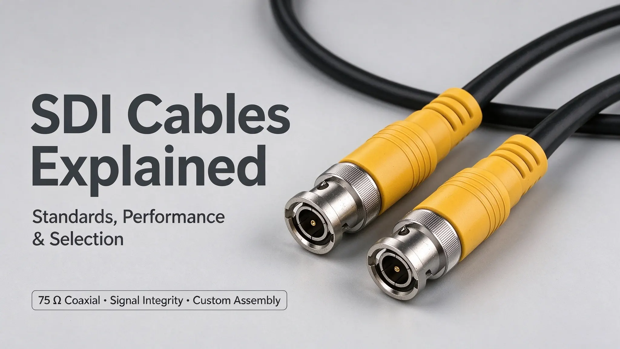
Serial Digital Interface (SDI) is a widely adopted digital video interface standard for professional broadcast, live production, medical imaging, and high-end surveillance systems. Designed for uncompressed, low-latency video and embedded audio transmission, SDI systems rely on 75Ω coaxial cable assemblies and impedance-matched connectors to maintain stable signal integrity in professional environments. HD and UHD production workflows require graded SDI specifications, and 12G-SDI is used in single-link UHD workflows requiring higher data rates. This guide systematically clarifies SDI standard definitions, cable structural specifications, performance testing criteria, core differences from similar interfaces, and professional cable assembly selection rules, providing actionable engineering references for system integrators, procurement engineers, and custom cable solution buyers.
1. What Is SDI? Standards and Basic Principles
Serial Digital Interface (SDI) is a complete family of digital video interface standards formulated and updated by SMPTE (Society of Motion Picture and Television Engineers), exclusively designed for professional uncompressed video and embedded audio transmission. It is critical to distinguish the interface standard from the transmission medium:
SDI signals are universally transmitted via customized 75Ω coaxial cable assemblies paired with impedance-matched connectors. A qualified SDI cable assembly is not an ordinary coaxial cable—it must meet strict bandwidth, return loss, attenuation, and signal integrity requirements corresponding to specific SDI data rates, ensuring stable long-distance transmission without signal distortion or data loss.
2. SDI Standards and Corresponding Data Rates
SMPTE has launched a complete iterative SDI standard system, covering different resolution and scenario requirements. Each specification corresponds to a fixed nominal bit rate and bandwidth requirement, which serves as a key reference for cable selection. However, the maximum practical transmission distance is not determined by the SDI standard alone—it depends on cable attenuation, connector performance, and receiver equalization capability. The following summary covers several commonly used SDI standards and their nominal bit rates for professional video workflows:
-
SD-SDI (SMPTE ST 259): Features nominal bit rates of 143Mbps and 270Mbps, corresponding to different standard-definition video formats for traditional SD broadcast systems
-
HD-SDI (SMPTE ST 292): Common nominal bit rate of 1.485Gbps, with a 1.485/1.001 rate system for frame-rate adapted formats, widely used in 1080i high-definition video production
-
3G-SDI (SMPTE ST 424): Nominal bit rate of 2.97Gbps, paired with a 2.97/1.001 rate system for adaptive video formats, supporting 1080p full HD video transmission
-
6G-SDI: Nominal bit rate of 5.94Gbps, designed for mid-band UHD video transmission, balancing bandwidth consumption and transmission stability
-
12G-SDI (SMPTE ST 2082-1): Nominal bit rate of 11.88Gbps, the mainstream single-link transmission standard for 4K UHD professional video workflows
The appropriate SDI configuration depends on the video format, interface capabilities, and system architecture. Some UHD workflows use multiple lower-rate links or other interface configurations rather than a single 12G-SDI connection.
3. Cable Construction and Electrical Performance
The stable signal performance of SDI cable assemblies relies on three core structural and electrical attributes: precise impedance control, low high-frequency attenuation, and reliable shielding performance. Professional SDI cable assemblies should be selected according to the target data rate, characteristic impedance, attenuation, return loss, installation conditions, and required link performance. Cable manufacturers publish product-specific electrical specifications that can help engineers evaluate suitability for a given application.
3.1 Fixed 75Ω Characteristic Impedance
SDI interfaces are designed around a nominal 75 Ω transmission path. Maintaining impedance continuity across the cable, connectors, and connected equipment helps control signal reflections and preserve overall signal integrity. Impedance discontinuities can increase signal reflections and degrade return loss. At higher SDI data rates, these effects may reduce the receiver's signal margin and contribute to link instability, depending on the overall channel and equipment characteristics.
3.2 Insulation and Attenuation Performance
SDI coaxial cables use insulation materials and geometries selected to meet their electrical and mechanical requirements. Some designs use foamed polyethylene (PE) to help reduce dielectric loss, while actual attenuation and propagation characteristics depend on the complete cable construction and operating frequency. Propagation delay and attenuation describe different aspects of cable performance. Both should be evaluated using the manufacturer's published specifications and relevant test conditions for the target SDI standard.
3.3 Shielding Structure and Mechanical Performance
SDI coaxial cables use different shielding constructions depending on their design and intended application. Foil shields, braided shields, or combinations of both may be used to suppress external electromagnetic interference and maintain long-term signal integrity. Shielding effectiveness cannot be judged merely by shielding coverage rate. When selecting a cable, engineers need to evaluate the manufacturer's specified shielding construction comprehensively, together with key indicators such as attenuation, return loss, and mechanical flexibility adapted to actual installation scenarios.
3.4 Compatible Connector Types
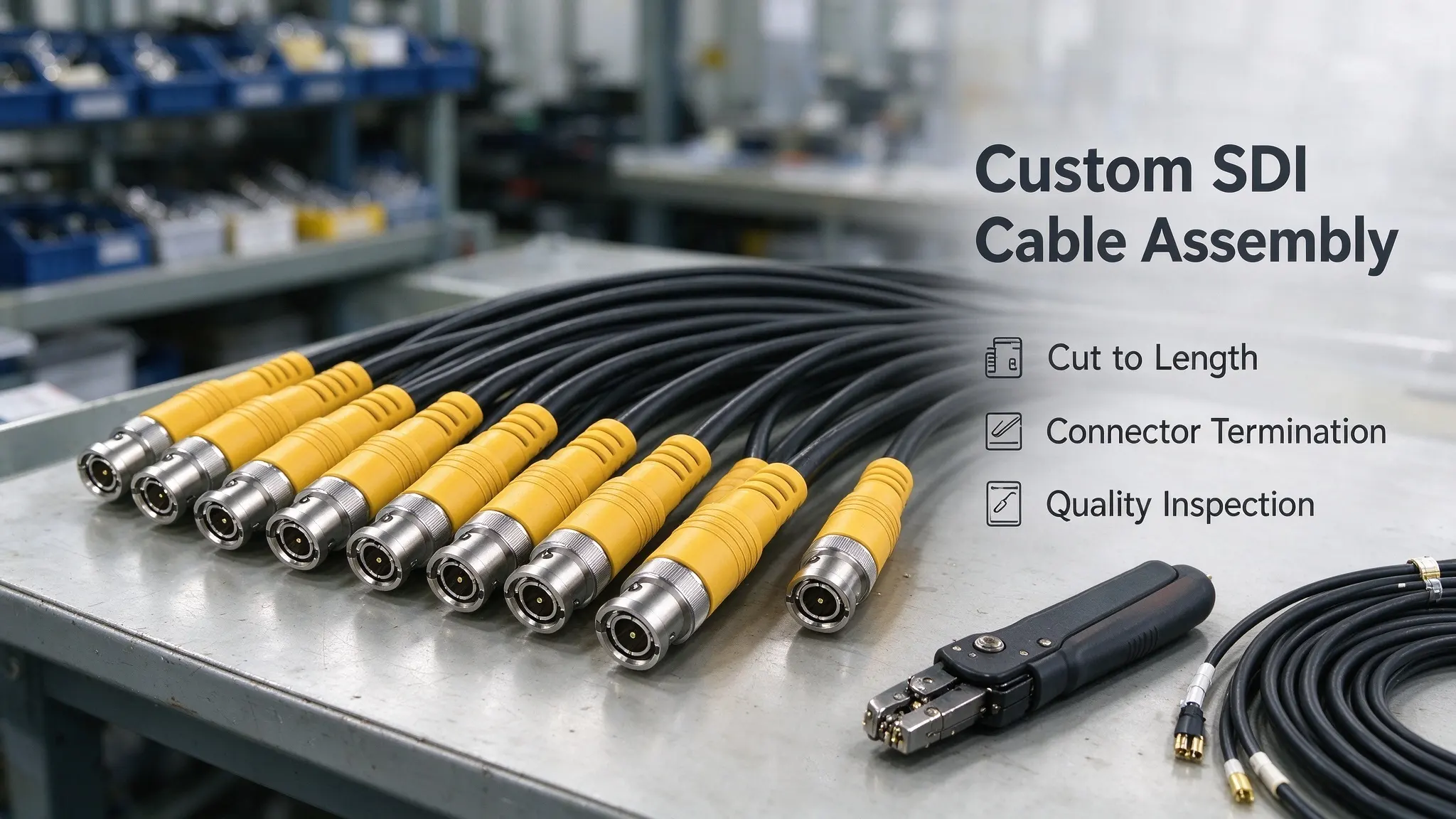
75Ω BNC bayonet connectors are the most common matching interface for SDI systems, featuring fast locking and stable contact. In addition to traditional BNC, compact professional interfaces such as HD-BNC and DIN 1.0/2.3 are also widely used in miniaturized professional equipment. Connector selection must strictly match 75Ω impedance and support the corresponding SDI rate to avoid signal mismatch failure.
4. SDI vs. Coaxial Cable, HDMI and BNC: Technical Differences
Industry confusion often arises from the mixing of SDI standards, cable structures, and connectors. This section accurately sorts the essential differences between the three groups of concepts to avoid engineering misapplication:
4.1 SDI vs. Generic Coaxial Cable
Coaxial cable refers to a general physical cable structure that can transmit analog or digital signals of various specifications. Not every coaxial cable is suitable for SDI transmission. However, suitability depends on the cable's characteristic impedance, frequency-dependent attenuation, return loss, and the performance of the complete cable assembly. A 75 Ω coaxial cable with qualified electrical characteristics may be suitable for SDI operation even if it is not explicitly marketed as a professional SDI cable. Ordinary civil coaxial cables usually fail to meet the strict high-frequency performance requirements of high-rate SDI transmission, so they are not recommended for professional SDI projects.
4.2 SDI vs. HDMI
Both interfaces transmit audio and video synchronous signals, but they are designed for completely different application scenarios, with no absolute advantage or disadvantage—only scenario adaptability differences:
-
SDI: Commonly used in professional broadcast, live production, and industrial video systems, paired with 75 Ω coaxial cabling and BNC/HD-BNC/DIN interfaces. Supported cable length and transmission stability depend on the SDI data rate, cable attenuation performance, connector quality, and receiver equalization capability.
-
HDMI: Primarily deployed for consumer and commercial display connections. The practical transmission reach of passive copper HDMI cables varies by data rate and cable design; active copper or optical fiber solutions are typically adopted for long-distance transmission scenarios.
4.3 SDI vs. BNC Connectors
BNC is a mature bayonet-lock radio frequency connector type, not an exclusive standard for SDI. Professional SDI systems mostly use 75Ω BNC connectors for stable connection, while miniaturized equipment can use HD-BNC and DIN 1.0/2.3 interfaces. The core of connector matching is impedance consistency and rate compatibility, not a single fixed connector type.
5. SDI Cable Testing: Signal Integrity, Jitter and Transmission Loss
SDI cable assembly verification can involve three levels of inspection: cable-level electrical characterization, system-level signal testing, and production inspection. The appropriate test methods depend on the product specification, intended application, and customer acceptance criteria. Ordinary cable continuity testing alone cannot verify whether a cable assembly supports high-rate SDI transmission.
5.1 Cable-Level Characterization Testing
Focus on physical and electrical performance indicators of the cable itself, including characteristic impedance, insertion loss, return loss, and full-band frequency response. Cable-level characterization evaluates these electrical parameters against the applicable product specifications and project requirements. Complete SDI link performance should be verified separately where required.
5.2 System-Level Signal Testing
Simulate actual operating scenarios to test system-level signal performance, including SDI signal locking stability, bit error rate (BER), signal jitter, and receiving end signal margin. These metrics depend on the full link environment and connected devices, rather than cable performance alone, and are not included in standard factory cable testing for general orders.
5.3 Production Batch Inspection
Conventional production inspection covers cable continuity testing, short-circuit testing, connector termination quality inspection, and visual appearance checks. Where required by the product specification or customer quality plan, high-frequency performance testing can be performed on representative samples or defined production lots to verify signal stability. The inspection frequency and acceptance criteria should be documented and confirmed before formal production to ensure product batch consistency.
6. How to Select a Custom SDI Cable Assembly
For engineering procurement and customized project scenarios, SDI cable selection cannot rely on empirical judgment alone. Reasonable component matching must be based on SDI standard specifications, cable attenuation parameters, connector impedance consistency, and on-site operating conditions. Referencing authoritative engineering guidelines from Belden and Canare, this section summarizes standardized selection processes to help buyers and system integrators accurately match qualified custom cable assemblies for specific project needs.
6.1 Confirm Core SDI Standard & Bandwidth Requirements
Determine the applicable SDI standard and link configuration, such as HD-SDI, 3G-SDI, 6G-SDI, or 12G-SDI, based on the video format, frame rate, color sampling, bit depth, equipment capabilities, and required transmission distance.
6.2 Match Cable Model & Transmission Distance
The practical transmission distance of any SDI signal is determined by cable attenuation characteristics, connector performance, wiring length, and receiver equalization capability. For 12G-SDI applications, select a 75 Ω coaxial cable assembly with documented high-frequency performance appropriate for the target link length and connected equipment. Lower-loss cable models may be necessary for longer runs or systems with limited equalization capability.
6.3 Determine Connector Configuration & Impedance
Select BNC/HD-BNC/DIN connectors according to the terminal equipment interface, and strictly ensure 75Ω impedance matching. Custom assemblies can be supplied with the same or different connector types at each end, depending on the equipment interfaces and on-site installation constraints.
6.4 Adapt to On-Site Installation Environment
Distinguish fixed installation and mobile use scenarios: fixed wiring prioritizes crush-resistant and high-stability models; mobile live production requires flexible stranded conductor cables to resist repeated bending damage. Outdoor projects need to match waterproof and weather-resistant sheath materials.
6.5 Verify Factory Testing & Custom Capabilities
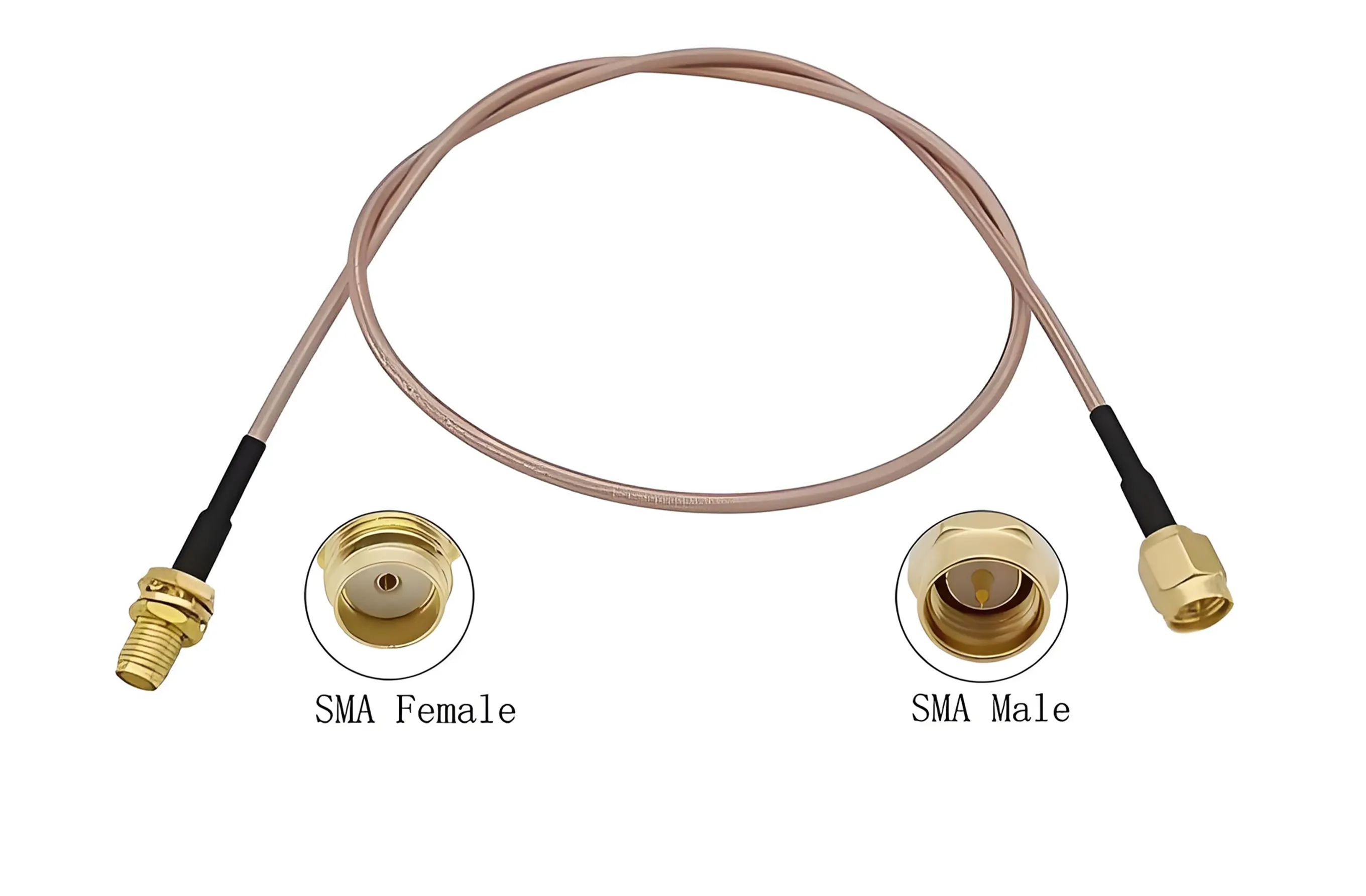
Professional suppliers provide reliable custom cable assembly services, including fixed-length cutting, precision multi-type connector termination, and standardized factory batch inspection. We support sample verification, small-batch trial production, and volume production of custom cable assemblies. Test records or reports can be provided according to the agreed inspection scope and customer requirements, ensuring products meet project-specific electrical and mechanical performance standards.
|
Required Parameter
|
Detailed Requirement Description
|
|---|---|
|
SDI Standard
|
Specify applicable specification: HD-SDI / 3G-SDI / 6G-SDI / 12G-SDI, determined by project resolution and bandwidth requirements
|
|
Cable Length
|
Confirm single cable length, total wiring distance, and number of connection nodes to avoid signal loss caused by excessive splicing
|
|
Cable Model
|
Specify designated brand and model, or entrust the supplier to recommend matching models according to SDI rate and attenuation requirements
|
|
Connector Configuration
|
Clarify terminal interface type (BNC/HD-BNC/DIN), gender, and installation space restrictions to ensure impedance matching
|
|
Application Environment
|
Distinguish fixed indoor installation, mobile live shooting, outdoor waterproof and weather-resistant scenarios, to confirm cable sheath and structural requirements
|
|
Acceptance & Testing Requirements
|
Clarify customized inspection standards: basic continuity and short-circuit testing, cable-level high-frequency performance verification (insertion loss, return loss), and optional system-level SDI signal testing (jitter and BER verification) with official test report requirements
|
7. FAQ: Frequently Asked Questions About SDI Cables
Q1: What is the maximum effective transmission distance of SDI cables?
The practical transmission distance is not a fixed value. It depends on four core factors: SDI signal rate, cable high-frequency attenuation performance, connector contact quality, and the equalization capability of the receiving equipment. High-quality low-loss cables can achieve longer transmission distances under the same standard. For key engineering projects, it is necessary to refer to the manufacturer’s official test data and complete on-site link verification.
Q2: Can SDI cables transmit audio signals simultaneously?
SDI supports embedded audio in compatible formats, allowing supported audio channels to be transported alongside video over the same connection without additional wiring. The available audio channel count and specific audio formats depend on the applicable SDI specification and the functional capabilities of the connected professional equipment.
Q3: Can SDI and HDMI signals be directly interconnected and used interchangeably?
SDI and HDMI use completely different physical interfaces and signal transmission formats, so their ports cannot be directly connected or interchangeable. An appropriate SDI-to-HDMI or HDMI-to-SDI converter is required for cross-standard signal conversion, depending on the signal transmission direction and the supported formats of the front and rear equipment.
Q4: Do SDI cable assemblies need regular replacement and maintenance?
For frequently used mobile cables or assemblies exposed to harsh industrial and on-site production environments, regular visual inspection and performance checks are recommended. If intermittent signal loss, unstable equipment locking, video flickering, or visible physical damage (jacket wear, loose connectors) occurs, inspect the complete transmission link and replace the cable assembly if professional testing confirms performance degradation.
Conclusion
SDI cable assemblies are professional-grade transmission carriers built for SMPTE SDI series standards, dedicated to uncompressed low-latency video and embedded audio transmission for professional scenarios. Stable SDI system operation relies on standardized standard matching, reasonable cable structure selection, accurate impedance matching, and rigorous performance verification. By evaluating core indicators including SDI data rate, cable high-frequency attenuation, connector compatibility, and on-site testing requirements, engineers can scientifically select suitable custom SDI cable assemblies and effectively avoid link instability, signal loss, and transmission failure risks in broadcast, medical, and surveillance projects.