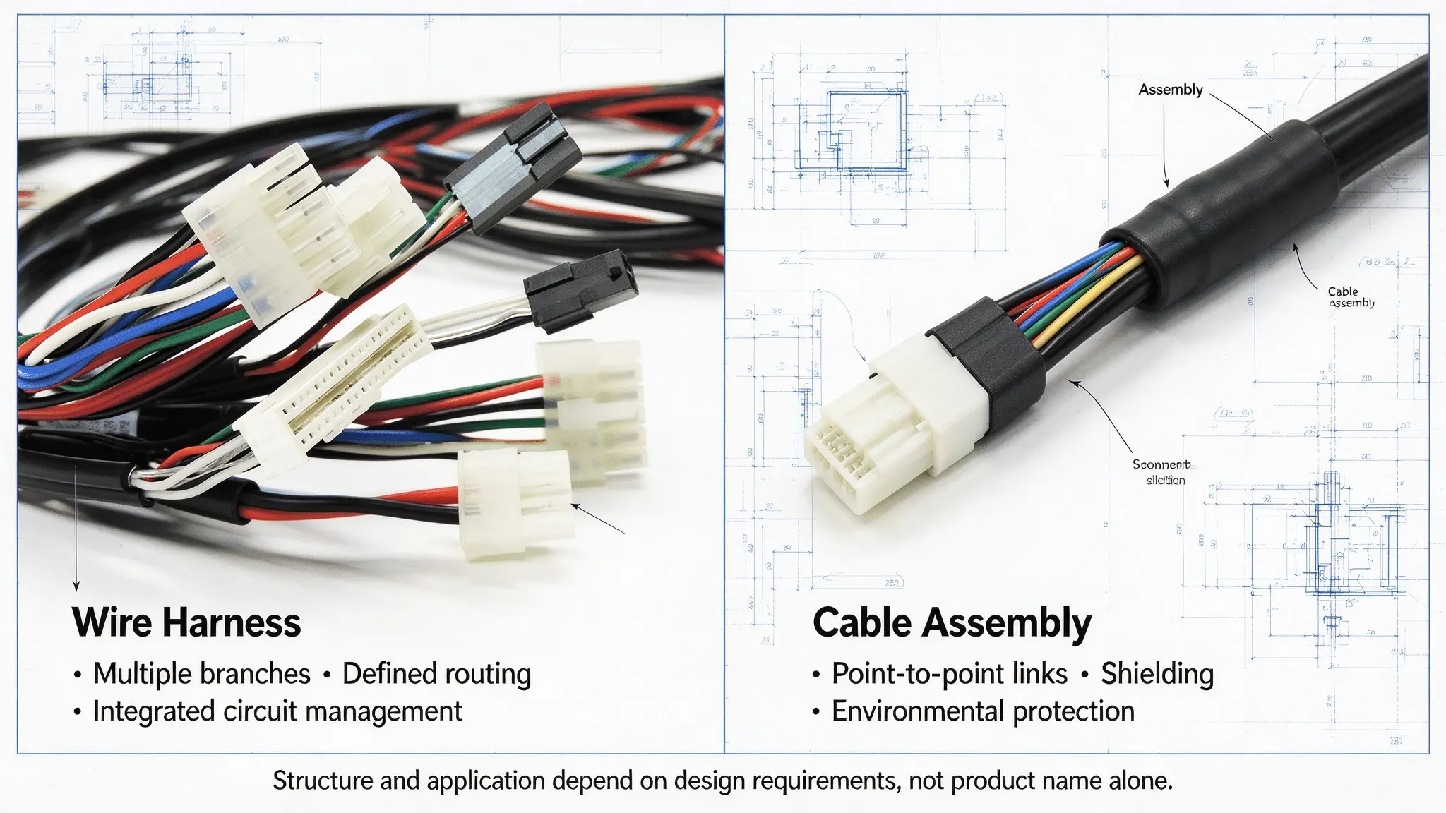
Wire harnesses and cable assemblies both deliver power and signal interconnection for electrical and electronic systems. While often grouped together in product documentation, their structural flexibility, installation and environmental requirements, and manufacturing workflows differ substantially. For OEM design and procurement teams, misaligned interconnect selection commonly causes inaccurate quoting, difficult on-site installation, insufficient environmental protection, and higher long-term maintenance costs. Rather than choosing by product name alone, engineers should base decisions on four practical project variables: connection topology, routing geometry, operating environment, and required validation scope. This guide explains practical selection criteria, manufacturing constraints, and RFQ preparation requirements to help engineers and procurement teams define a suitable manufacturing approach.
1. Start with the Application, Not the Product Name
The most common selection error is matching projects to generic product labels instead of actual design requirements. Wire harnesses and cable assemblies have overlapping capabilities, with no strict distinction between the two across all industrial applications. To eliminate misselection, qualify your project through four targeted engineering questions before locking in a solution.
-
What are you connecting? Multiple internal components or separate devices?
-
How complex is the routing? Are branches, mounting points, or variable wire lengths required?
-
What environment will it operate in? Will it face moisture, oil, vibration, abrasion, or UV exposure?
-
What validation is required? Are shielding, signal integrity, electrical safety, or lifecycle tests specified?
For a basic comparison of their structures and typical applications, see our guide to the differences between wire harnesses and cable assemblies.
2. When Should You Choose a Wire Harness?
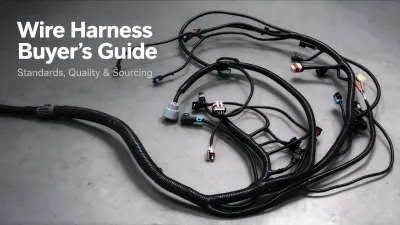
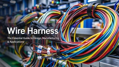
Wire harnesses are typically preferred for complex, multi-branch interconnection systems that benefit from centralized wiring management and standardized assembly. They excel at consolidating dispersed circuits into a single, prefabricated unit, streamlining mass production, consistent on-site installation, and systematic circuit troubleshooting for industrial and commercial equipment.
Multiple Circuits and Branch Connections
For systems integrating multiple sensors, actuators, control modules, and power nodes, wire harnesses consolidate individual circuits into a unified assembly with defined branch positions and connector locations. This arrangement standardizes routing and installation across production batches, reducing on-site wiring work and helping maintain consistent assembly quality.
Complex Routing Inside Equipment
Industrial control cabinets, automated robotics, automotive electrical systems, and precision machinery often require constrained internal routing with fixed pathways and directional connector placement. Custom wire harnesses support variable wire lengths, required bend allowance and minimum bend radius, and pre-positioned mounting clips and brackets. Prefabricated routing aligns with standard equipment mechanical envelopes, optimizing limited internal space and delivering consistent, repeatable wiring layouts across production batches.
Installation and Maintenance Considerations
Custom wire harnesses may incorporate color-coded conductors, wire identification labels, mounting clips, brackets, and other routing accessories to simplify installation and reduce wiring errors. In service and maintenance scenarios, the structured branch layout simplifies fault localization and targeted component replacement. Individual branch replacement is feasible depending on connector design, harness segmentation, and fixed mounting configuration, making structured harness layouts ideal for long-term production and maintainable system designs.
3. When Is a Cable Assembly the Better Choice?
Cable assemblies are commonly used for point-to-point connections between devices, modules, or electrical interfaces. Depending on the design, they may incorporate single-core or multi-core cables, multiple connectors, shielding, overmolding, and branch connections. The appropriate configuration depends on the electrical requirements, mechanical layout, and environmental conditions of the application, delivering tailored transmission performance and mechanical protection for targeted use cases.
Point-to-Point Electrical Connections
Cable assemblies excel at structured, controlled interconnections for sensor signal lines, equipment power cables, industrial Ethernet links, and low-voltage communication wiring. Each assembly is engineered for a defined transmission path, stabilizing power and signal delivery while minimizing cross-circuit interference. Both single-path and multi-branch cable assemblies are available, making them adaptable for modular equipment designs and standardized system architectures.
Shielding, Jacket and Connector Requirements
High-performance cable assemblies often utilize application-specific features including full or partial shielding layers, durable outer cable jackets, engineered strain relief structures, and overmolded connector terminations. Overmolding and strain relief designs mitigate mechanical stress at connection points, while shielding configurations address EMC and signal integrity requirements. These protective features are optional and customized per project, with effectiveness verified through applicable testing based on material grades, structural design, and project specifications.
Applications Requiring Environmental Protection
With customizable waterproof, oil-resistant, and UV-stabilized materials paired with sealed connector interfaces, cable assemblies adapt to harsh operating conditions including outdoor deployment, dynamic mechanical movement, and humid industrial environments. Environmental performance is not inherent to the product type but derived from material selection, sealing design, and validated test results. A properly designed cable assembly can provide the environmental protection required for a specific application when its materials, sealing interfaces, and validation results meet the defined operating conditions.
4. Five Engineering Factors That Determine the Right Solution
Engineering selection should account for both design requirements and manufacturing constraints. Before releasing a design, verify branch dimensions and connector orientations against the intended routing layout. Crimped terminal pull-force testing may be required by the applicable specification, while connector part numbers, keying features, and circuit assignments should match the released drawings and BOM. Shielded or high-speed assemblies may require additional signal integrity or shielding verification, depending on the interface and application.
Accurate solution selection relies on five core engineering dimensions that directly determine product structure, manufacturing processes, and acceptance criteria. These parameters help engineers select a solution based on measurable project requirements. Critical details such as connector keying, impedance control, and shield termination further refine build requirements for high-reliability industrial projects.
|
Selection Factors
|
Key Confirmation Content & Manufacturing Impact
|
|---|---|
|
Electrical requirements
|
Confirm rated voltage, operating current, conductor size, and signal type. Conductor sizing and insulation selection should account for current capacity, temperature rise, voltage rating, and installation conditions. High-speed or high-frequency applications may require controlled impedance, appropriate shielding, and suitable termination design based on interface specifications and signal integrity requirements.
|
|
Routing and geometry
|
Evaluate branch quantity, total wire length, dimensional tolerance, minimum bending radius, and spatial routing constraints. Complex multi-branch layouts with variable pathways typically benefit from wire harness integration. Short, fixed routing does not exclusively require cable assemblies; final selection depends on branch count, interface standardization, and maintainability requirements, which also determine custom tooling and cutting process specifications.
|
|
Environmental conditions
|
Evaluate operating temperature range, humidity, industrial oil corrosion, mechanical vibration frequency, and UV exposure. Harsh environments require modified jacket materials, sealed terminals, and anti-vibration fixed structures, raising requirements for raw material selection and post-processing processes.
|
|
Protection and interfaces
|
Confirm shielding grade, insulation requirements and applicable IP rating for the specified assembly or interface, waterproof and dustproof standards, and connector/terminal models. Custom interface matching and multi-layer shielding structures are often required for precision equipment, determining connector assembly and molding processes.
|
|
Quality and lifecycle
|
Define mandatory test regimes, service life expectations, batch traceability protocols, and field maintainability rules. Long-lifecycle industrial equipment requires strict terminal crimp quality control, pull-force verification, and batch consistency inspections. Enhanced process controls and full-unit testing are implemented for high-reliability applications to meet sustained operational performance standards.
|
5. Practical Selection Decision Table (By Project Condition)
Use the following table as an initial screening tool. The final configuration should be confirmed against the project’s electrical, mechanical, and environmental requirements.
|
Project Condition
|
Recommended Solution Priority
|
Key Verification Items Before Finalization
|
|---|---|---|
|
Multiple internal components requiring branched connections (multi-sensor/actuator systems)
|
Wire Harness
|
Branch dimensions, mounting points, connector orientation, connector compatibility and circuit assignment
|
|
Independent point-to-point links between two separate devices/modules
|
Cable Assembly
|
Connector mating specs, cable gauge, finished length tolerance, and strain relief design
|
|
Electrically noisy environments for precision signal transmission
|
Application-Dependent (Evaluate Both)
|
Shield coverage, termination method, impedance requirements where applicable, and required EMC validation
|
|
Outdoor, humid, or oily industrial operating environments
|
Application-Dependent (Evaluate Both)
|
Jacket material rating, sealed connector IP grade, UV resistance, and validated environmental test data
|
|
Complex branched layouts + harsh environmental protection requirements
|
Custom wire harness or cable assembly with integrated protective features
|
Branch sealing process, localized overmolding, fixed mounting durability, EMC performance, and required signal/environmental performance validation
|
6. How Design Choices Affect Manufacturing Cost
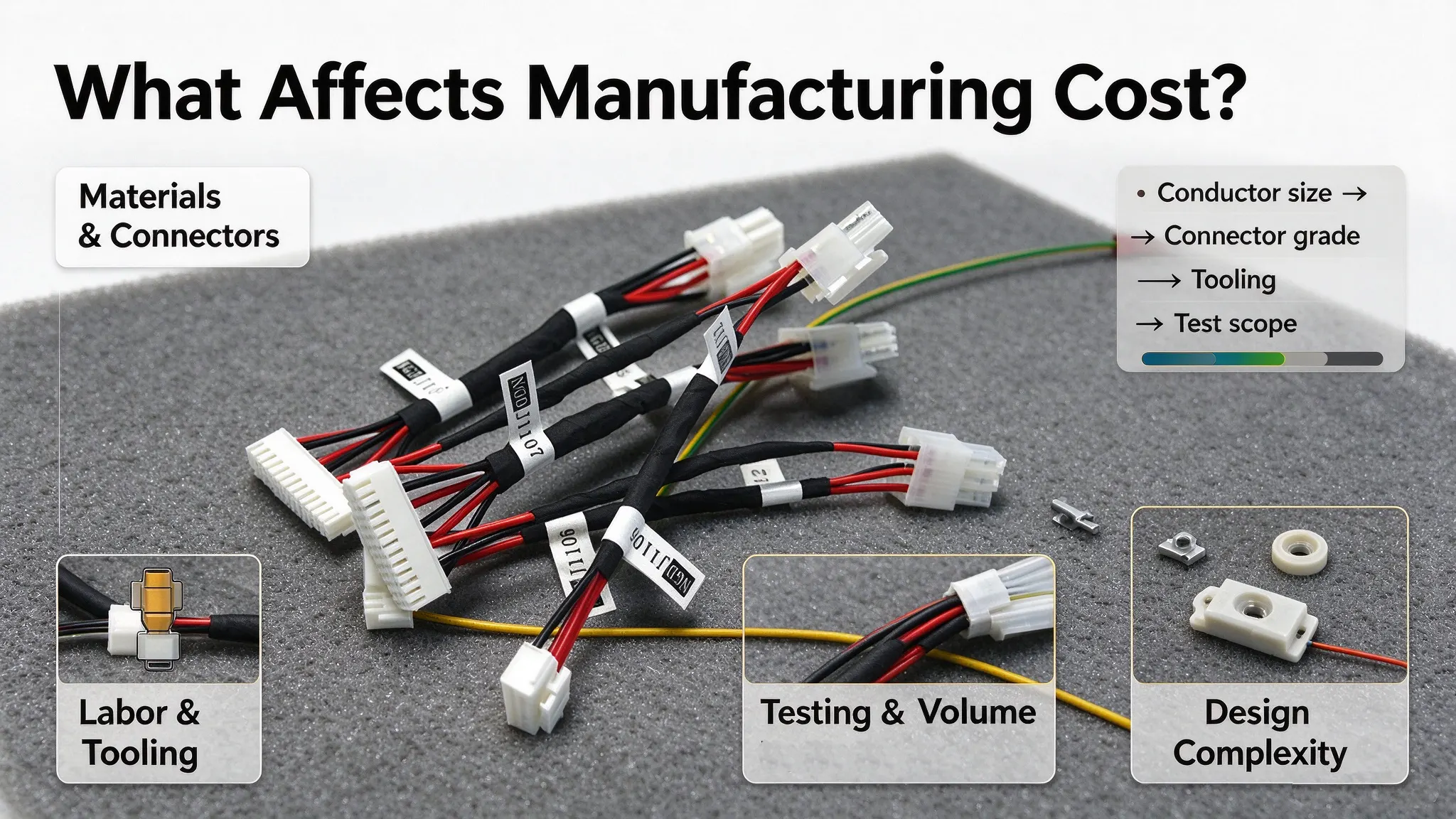
Many procurement teams compare unit pricing based solely on product categories, though actual project costs are driven by customized design parameters, not product names. Material costs can be a major part of the total cost, but their share varies with connector selection, assembly complexity, production volume, tooling requirements, and inspection scope. Understanding these cost drivers prevents unfair price comparisons and enables data-driven design tradeoffs.
Material and Connector Cost Variables
Material costs depend on conductor size, cable construction, insulation and jacket materials, shielding requirements, connector series, terminal specifications, and sealing components. Specialized materials and application-specific connectors can increase unit costs, while the required cable length and material utilization also affect total consumption. The actual cost contribution of each item varies by design and order volume.
Assembly Labor & Custom Tooling Overhead
Complex wire harnesses with multiple branches require manual sorting, positioning, and layered assembly, increasing assembly time and labor requirements. Custom routing layouts and special branch positions need customized harness board tooling and positioning jigs. For cable assemblies requiring integral molding and special stress relief structures, dedicated injection molds and processing equipment are necessary, raising fixed production costs.
Testing Requirements & Production Scale Amortization
Comprehensive testing (continuity, insulation resistance, dielectric withstand, signal stability) improves product reliability but extends cycle time and increases inspection costs. Small-batch prototype orders incur higher per-unit tooling, setup, and testing overhead, while mass production amortizes fixed engineering and tooling expenses to lower unit pricing. For accurate cost benchmarking, always compare quotes under identical material specifications, process controls, and validation scopes.
7. What Information Should You Send for an Accurate Quote?
Incomplete RFQ documentation is a leading cause of quote discrepancies, delayed deliveries, and design revisions. To receive an accurate, manufacturable quotation, engineering and procurement teams should submit key project details upfront. The checklist below covers the key information commonly needed for an initial quotation and engineering review.
Design and Layout Files
2D engineering drawings, 3D models, or detailed wiring diagrams; clear marking of branch locations, routing paths, fixed mounting points, and mechanical dimensional tolerances.
Components and Interfaces
Complete bill of materials (BOM), including approved part numbers; matched connector pairs, connector keying and polarization features, and standardized terminal specifications.
Cable Specifications and Dimensions
Wire or cable type, conductor size (AWG or metric equivalent), insulation grade, and shielding configuration requirements; finished cable length and measurement reference points, and allowable dimensional tolerances.
Electrical and Environmental Requirements
Rated voltage, working current, and signal transmission type; continuous operating temperature range; required IP rating for the specified assembly or interface, chemical/oil resistance, vibration resistance, and UV resistance requirements and applicable test methods.
Testing and Quality Requirements
Applicable industry standards and mutually confirmed acceptance criteria; required electrical tests including continuity, insulation resistance, and dielectric withstand testing; mandatory signal performance verification for high-speed assemblies; formal inspection records, batch traceability rules, and pre-production sample approval requirements.
Production and Delivery Terms
Prototype sample quantity, initial order volume, and estimated annual usage or production volume; target lead time, delivery schedule, packaging, and shipping requirements.
If your design is preliminary or partially finalized, submit available drawings, physical samples, or core functional requirements. Our engineering team can evaluate manufacturability, identify missing parameters, and confirm a suitable manufacturing approach aligned with your project constraints.
8. Manufacturing and Quality Checks Before Production
After finalizing a wire harness or cable assembly solution, standardized pre-production verification ensures batch consistency and compliance with project-specific requirements. Manufacturing and inspection processes follow applicable portions of the IPC/WHMA-A-620 standard where specified by project terms, alongside customer-defined acceptance criteria. No universal inspection regime applies to all custom products; test scopes and process controls are tailored to each project’s electrical, mechanical, and environmental demands.
Pre-production verification typically covers three areas: material conformity against the approved BOM and drawings; process readiness for operations such as wire stripping, crimping, soldering, and overmolding, where applicable; and inspection or electrical testing defined by the approved control plan. Typical electrical checks may include continuity, pin assignment, insulation resistance, or dielectric withstand testing, depending on product specifications and customer requirements.
Where required by the project or quality agreement, formal sample approval should be completed before mass production. The released drawing revision, BOM, inspection criteria, and applicable process requirements should be strictly controlled throughout production. IPC/WHMA-A-620 provides workmanship requirements and acceptance criteria for cable and wire harness assemblies. Its applicable provisions should be used alongside the released product drawings, customer specifications, and project-specific validation requirements. It does not replace separate environmental, EMC, or electrical performance testing where those tests are required.
An IP rating should be stated only for the specified assembly or interface configuration that has been evaluated under the applicable test conditions, rather than generalized for the entire product based solely on individual component specifications.
9. Frequently Asked Questions
Can a cable assembly include multiple branches? Yes. While cable assemblies are commonly associated with point-to-point connections, custom multi-branch cable assemblies are fully feasible. Both wire harnesses and cable assemblies support branched layouts, unified outer jackets, and targeted protective structures. Product selection depends on routing complexity and application requirements, not fixed structural limitations.
Can a wire harness use jacketed cables? Yes. A wire harness can incorporate jacketed, shielded, or high-temperature-rated cables. The additional protection and electrical performance depend on the cable construction, materials, shielding design, and installation conditions.
Which is more cost-effective: a wire harness or a cable assembly? No universal cost advantage exists for either product. Pricing depends on conductor specs, connector grade, process complexity, testing scope, and production volume. Simple point-to-point layouts may favor cable assemblies in some cases, while integrated harness designs can reduce overall system costs for complex multi-branch systems when evaluated under identical project conditions.
What information is needed to manufacture a custom wire harness or cable assembly? Accurate manufacturing requires wiring drawings, BOM lists, component specifications, electrical and environmental requirements, testing standards, and production batch demands. Incomplete information will lead to solution adjustments and quotation deviations.
Can wire harnesses and cable assemblies use the same connectors? Yes, both wire harnesses and cable assemblies can utilize identical connector families, provided the selected housings, terminals, wire sizes, electrical ratings, and environmental specifications are compatible with the intended application. Connector selection depends on system voltage/current capacity, signal type, installation environment, and wire size, rather than whether the final assembly is defined as a wire harness or cable assembly. Standardized connector families may support both assembly types to simplify procurement and system consistency.
10. Get Engineering Support for Your Custom Interconnect Project
Need help selecting a wire harness or cable assembly for your equipment? Send us your drawings, BOM, connector part numbers, or available product samples. Our engineering team can review routing constraints, electrical requirements, environmental conditions, and production volumes to assess manufacturability and prepare a project-specific quotation. Contact our team to discuss your custom wire harness or cable assembly requirements.