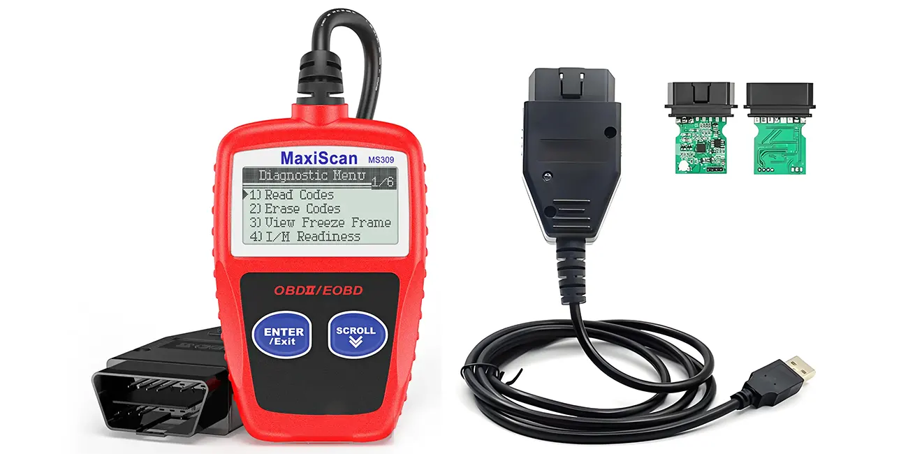
Modern light and medium-duty vehicles rely on distributed electronic control systems to manage engine performance, emissions and onboard functions. OBD II forms part of a regulatory onboard diagnostic framework built to capture emissions-related faults and expose real-time vehicle operating data. A well-engineered OBD II wire harness serves as a core automotive diagnostic solution, enabling stable data transmission for ECU communication between vehicle control units, scan tools, telematics hardware and production test equipment. OEM engineering teams, fleet operators and service technicians often select durable, custom OBD II wire harness solutions to match unique project requirements.
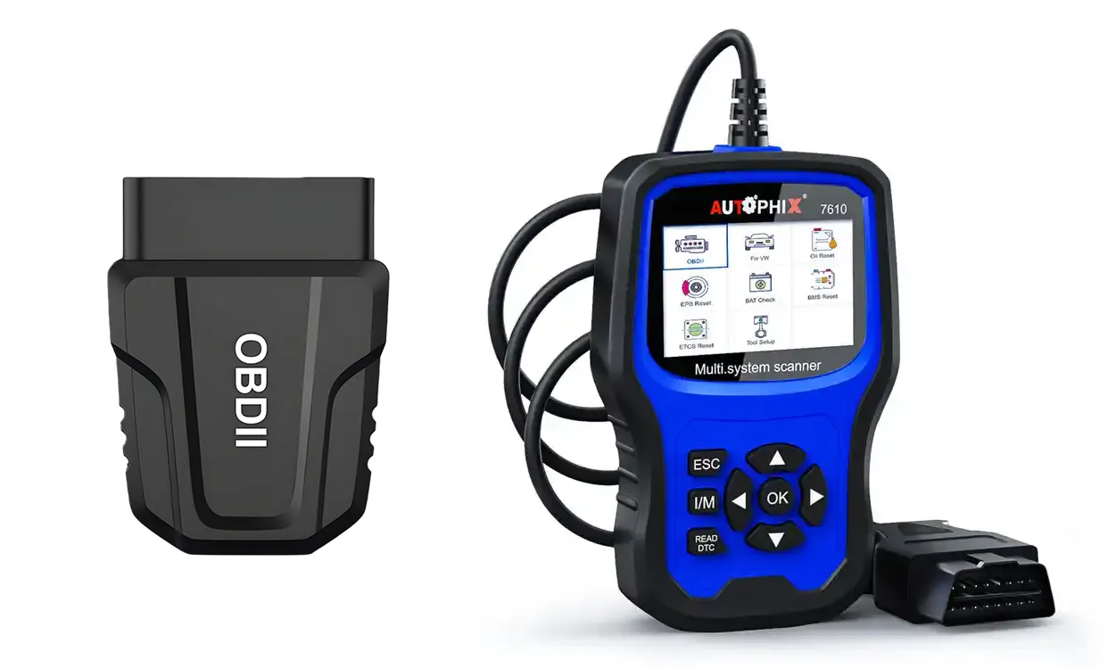
What Is OBD II?
OBD II (On-Board Diagnostics II) is the second-generation regulatory diagnostic framework and interface specification primarily applied to light and medium-duty vehicles. Its core purpose is to monitor systems tied to exhaust emissions, record fault events and present alerts to technicians and vehicle operators.
Core Functions of the OBD II System
Integrated with the vehicle ECU, the OBD II framework continuously monitors emission-related subsystems. When anomalies are detected, the system logs diagnostic trouble codes and triggers dashboard indicators. Commonly monitored subsystems include:
- Fuel injection system
- Ignition system
- Catalytic converter
- Oxygen sensors
- EVAP evaporative emission control system
- Other emission-related components
How OBD II Works
The SAE J1962 standard defines the physical 16‑pin diagnostic connector used for OBD II communications. This connector acts as the gateway to access ECU data. OBD II wire harness assembly is the wiring assembly that links this J1962 port to external diagnostic devices, telematics modules or test benches. Depending on the vehicle model, model year, and market, OBD II implementations may use communication protocols such as CAN, ISO 9141, ISO 14230 (KWP2000), or SAE J1850.
Professionally built OBD II wiring supports three core diagnostic workflows:
- Read and clear stored OBD DTC codes
- Transmit live engine parameters and sensor data
- Support vehicle service, diagnostic and, where applicable, ECU programming procedures
This standardized framework lets technicians use universal scan tools across most vehicle platforms, improving the consistency of diagnostics and maintenance.
OBD II Warning Lights and Basic Troubleshooting
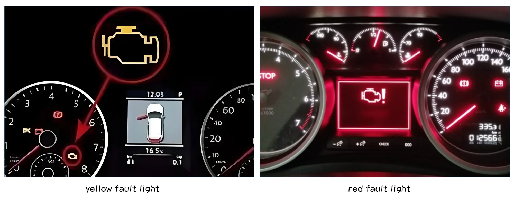
The Check Engine Light (MIL, Malfunction Indicator Lamp) communicates diagnostic status in distinct modes, and severity cannot be judged by the lamp color alone.
- Steady Check Engine Light: An emissions-related fault has been stored. The issue may range from minor to moderately serious. Road use may still be possible, but diagnostic scanning is recommended promptly to prevent secondary damage.
- Flashing Check Engine Light: Often indicates an active misfire condition that can damage the catalytic converter. Avoid continued driving and arrange prompt professional diagnosis.
- Separate red warning indicators: These are distinct from the MIL and typically signal non-emission critical faults such as oil pressure or overheating.
Standard OBD II troubleshooting workflow:
- Connect a professional diagnostic scanner via an OBD II extension harness to maintain stable signal transfer
- Retrieve OBD DTC codes to narrow down faulty components or circuit issues
- Replace defective hardware or schedule professional repair for complex faults
What Is an OBD II Wire Harness?
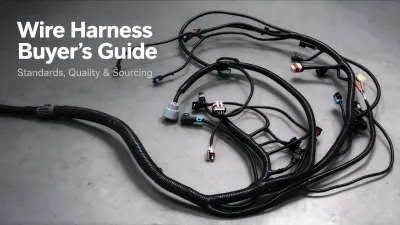
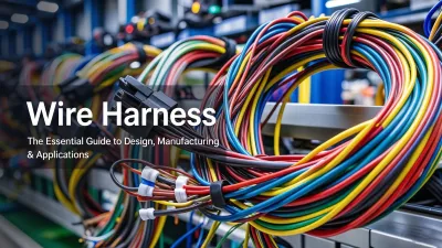
An OBD II wire harness assembly is a prefabricated wiring solution built to connect the vehicle’s J1962 diagnostic port to external hardware. It typically consists of insulated conductors, terminals, connector housings, and, where required, seals or protective components. Conductor material, insulation, terminal plating, shielding, and connector configuration are selected according to the vehicle application and electrical requirements.
A high-quality OBD II wiring assembly fulfills three core roles within vehicle electronic workflows:
- Stably transmit diagnostic data and OBD DTC fault records
- Deliver consistent power and ground for external diagnostic peripherals
- Preserve signal integrity for continuous live vehicle monitoring
These assemblies are essential hardware for end-of-line vehicle testing, aftermarket service and emissions compliance inspections.
OBD II Wire Harness Technical Specifications
The following core specifications cover standard design and manufacturing considerations for mainstream OBD II wire harness applications, guiding engineers and purchasers in project customization:
|
Parameter
|
Typical Specification & Consideration
|
|
Connector Standard
|
SAE J1962 16-pin standardized diagnostic connector, customizable for special vehicle models
|
|
Supported Protocols
|
CAN bus, K-Line (ISO 9141), KWP2000 (ISO 14230), SAE J1850 (model/region dependent)
|
|
Conductor Material
|
Tinned copper or bare copper, selected based on corrosion resistance and electrical conductivity requirements
|
|
Wire Gauge
|
Matched to working current, cable length and voltage drop standards for automotive applications
|
|
Insulation Material
|
Automotive-grade PVC, XLPE, TPE, adapting to high-temperature and vibration vehicle environments
|
|
Shielding Design
|
Optional twisted pair shielding, configured for high EMI/EMC interference scenarios
|
|
Quality Testing
|
Continuity test, short-circuit test, insulation resistance test, crimp pull-force verification, visual inspection
|
OBD II Wire Harness Design Logic Example
Standard OBD II wire harness design follows fixed vehicle circuit logic to ensure stable signal and power transmission. The basic connection framework for conventional diagnostic harnesses is as follows:
- Vehicle SAE J1962 Diagnostic Port ├─ Power Circuit (Vehicle Battery Power Supply) ├─ Ground Circuit (Vehicle Common Ground) ├─ CAN-H / CAN-L Differential Signal Pair (Main Diagnostic Communication) └─ Reserved Diagnostic Signal Lines (K-Line, Auxiliary Detection)
All pin assignments, circuit configurations and line definitions must be verified against the target vehicle model, year and equipment specifications. This standardized design framework ensures compatibility with mainstream diagnostic tools, test bench equipment and telematics modules, while customizable modifications support personalized project needs.
Key Design Considerations for OBD II Harnesses
Engineers specify OBD II wiring assemblies with signal integrity, mechanical durability and automotive environmental requirements in mind. Critical design points include:
- Connector and Pin Configuration: J1962 pinout must match the intended use case, whether for simple power tapping, CAN bus readout or full diagnostic pass‑through. Pin assignments must align with target vehicle ECU definitions.
- Wire Gauge and Current Requirements: Conductor size is selected based on supply current, cable length and voltage drop limits. Telematics add‑on circuits often require dedicated fused power paths.
- CAN / K-Line Signal Integrity: CAN wiring generally uses twisted differential pairs to help maintain signal integrity. Shielding may be specified for applications with higher EMI/EMC requirements, ensuring stable communication in complex vehicle electrical environments.
- Terminal Crimp Quality: Crimp geometry, pull resistance and electrical contact resistance are controlled during manufacturing to avoid intermittent faults from vibration and thermal cycling.
- Mechanical Protection and Strain Relief: Strain relief at connector entry points prevents wire breakage during repeated plug/unplug cycles, especially important for test bench harnesses that see frequent mating.
OBD I vs OBD II: Side-by-Side Comparison
The shift from OBD I to OBD II standardized vehicle diagnostics across manufacturers. The table below highlights core differences:
|
Feature
|
OBD I
|
OBD II
|
|
Diagnostic Standardization
|
Limited / manufacturer-specific
|
More standardized across vehicles
|
|
Connector Interface
|
Brand-specific proprietary connectors
|
Standardized 16-pin J1962 diagnostic connector
|
|
DTC Fault Codes
|
Non-standard manufacturer-only codes
|
Standardized diagnostic trouble code structure, including P0xxx and manufacturer-specific P1xxx codes
|
|
Emissions Monitoring
|
Limited coverage
|
More comprehensive emissions-related monitoring
|
|
Data Access
|
Restricted fault reporting
|
More standardized access to diagnostic trouble codes and live data
|
|
Malfunction Indicator
|
Inconsistent or missing warning lights
|
Standard universal Check Engine light
|
OBD II addresses many limitations of older OBD I implementations, creating a common diagnostic interface for service, compliance and vehicle telematics.
Common Applications for OBD II Wire Harness Assembly
Automotive OEM End-of-Line Production Testing
OEM assembly lines use OBD II test harness assemblies for end-of-line vehicle validation. These wiring products are built to withstand repeated mating cycles, test bench routing and vibration. The design prioritizes connector retention, strain relief and stable CAN communication. Custom assemblies connect industrial test PCs to vehicle J1962 ports to run ECU flashing, DTC scans and emissions system verification, reducing intermittent signal loss and false test failures.
Auto Repair Shops & Aftermarket Diagnostics
Independent service garages use OBD II extension harness and splitter wiring for live road testing. Extended harnesses let technicians keep scan tools connected while driving, capturing real-time operating data to isolate intermittent faults. Custom pin‑modified assemblies also fit older and specialty vehicles where off‑the‑shelf cables do not match the required pinout.
Commercial Fleet & Telematics Deployment
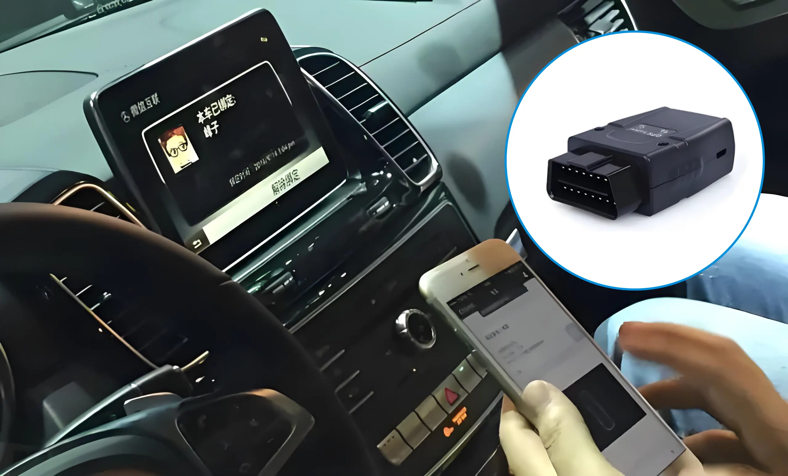
Fleet telematics installations often use OBD Y‑splitter harness designs. The pass‑through architecture preserves access to the factory J1962 port for official inspections while feeding power and vehicle data to GPS and telematics trackers. Built‑in power protection guards connected modules. Operators retrieve real‑time engine data, location, idle time and harsh driving events, and receive DTC alerts to schedule preventive maintenance and reduce vehicle downtime.
Vehicle R&D and Test Bench Validation
Automotive engineering teams rely on custom OBD II wiring to connect ECU simulators, high-speed data loggers and scan tools in lab environments. These assemblies support simulated drive cycles, DTC trigger validation and CAN bus troubleshooting before road testing, supplying consistent and repeatable data for electronic system refinement.
Emission Inspection and Compliance Testing
Inspection agencies use certified OBD II wiring assemblies for emissions compliance audits. Test equipment connects via the harness to pull fault codes and confirm proper function of emission-related subsystems for mandatory safety and environmental checks.
How to Customize an OBD II Wire Harness
When requesting a custom OBD II wiring assembly, the engineering team requires the following technical details for accurate quotation and design review:
- Connector part number and housing specifications
- Pinout table or wiring diagram
- Wire type, insulation material and conductor gauge
- Finished assembly length
- Terminal type and plating requirements
- Shielding and twisted-pair requirements for communication lines
- Operating temperature range and environmental exposure
- Current rating and fuse/protection requirements
- Target communication protocol
- Engineering drawing or physical sample (if available)
- Expected annual production volume
With a drawing, sample or connector part number, engineering teams can review harness specifications before formal quotation.
Engineering & Manufacturing Capabilities for Custom Wire Harness Assembly
Professional automotive wiring suppliers deliver OBD II assemblies through structured engineering, production and quality workflows:
Engineering Phase
- Pinout review and connector matching
- Wire gauge and voltage drop calculation
- Terminal and crimp selection
- DFM (Design for Manufacturability) review
- 2D drawing confirmation and prototype validation
Manufacturing Phase
- Precision wire cutting and stripping
- Automated and manual terminal crimping
- Connector assembly and strain relief installation
Quality Verification
- First article inspection for prototype batches
- 100% electrical continuity and short-circuit testing
- Crimp pull-force verification performed per defined quality procedures
- Insulation resistance testing as required by project specs
- Visual inspection and production traceability
Finished assemblies can be manufactured using materials and processes aligned with applicable RoHS and REACH requirements. Our quality management system is based on ISO 9001 standards, with automotive-grade production and testing protocols tailored to match specific project and industry requirements.
FAQ
Q1: Can OBD II wire harness assemblies be customized for specific diagnostic protocols?
A: Yes. Custom wiring assemblies can be engineered to support CAN-BUS, ISO 14230 (KWP2000), and other common automotive diagnostic protocols to match project specifications.
Q2: What insulation materials are used for automotive OBD II harness assemblies?
A: Automotive wire harnesses may use UL-recognized or application-specific PVC, XLPE, TPE and other insulation constructions, with tinned or bare copper conductors selected according to the electrical and environmental requirements of each project.
Q3: Can custom OBD II harness assemblies integrate telematics hardware?
A: Yes. OBD telematics harnesses can include independent power circuits for GPS modules, with optional fuse and over-current protection tailored to project needs.
Q4: What is the typical MOQ for custom OBD II wire harness orders?
A: MOQ depends on connector, terminal, tooling and testing requirements. Small prototype quantities can be discussed for new development projects.
Q5: What is the difference between an OBD II cable and an OBD II wire harness?
A: A simple OBD II cable is typically a basic two-ended wiring jumper. An OBD II wire harness assembly may include multiple branches, splices, fuses, strain relief, shielding and multiple connectors built as one integrated wiring system.
Q6: What information is needed to quote a custom OBD II harness?
A: Connector part numbers, pinout diagram, wire gauge, assembly length, environmental specs and expected volume are the core inputs. Drawings or physical samples help speed up technical review.
Conclusion
OBD II remains the primary onboard diagnostic framework for modern light and medium vehicles. Reliable ECU data access and diagnostics depend on well-designed OBD II wire harness assembly. These custom wiring solutions serve OEM production, R&D, aftermarket repair, fleet telematics and emissions inspection use cases. If you require an OBD II wiring assembly built to your vehicle or bench specifications, submit your technical documentation for a detailed review and quotation.