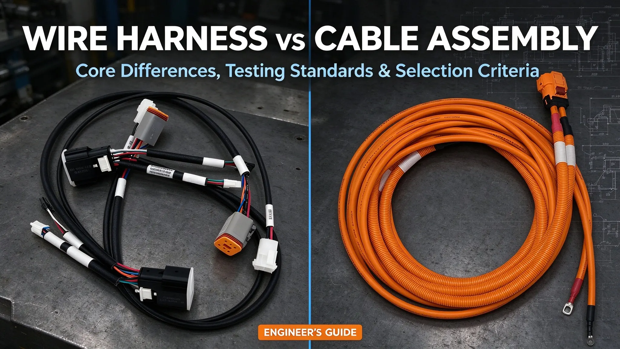
Wire harnesses and cable assemblies are core customized wiring components for electrical and electronic systems, widely adopted in automotive, industrial automation, medical devices, robotics, and telecommunications industries. Due to overlapping functions in power delivery and signal transmission, these two terms are frequently confused in the industry.
The key difference between wire harnesses and cable assemblies lies in structural design and application scenarios, not simplistic differences in power, frequency, or durability. This guide summarizes clear definitions, manufacturing rules, test standards, and practical selection logic to help engineers and buyers make project-based decisions.
1. Core Definition & Manufacturing Build Logic
What Is a Wire Harness?
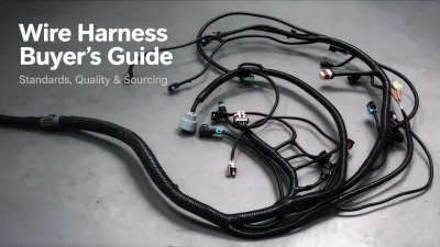
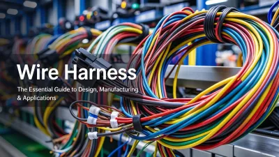
A wire harness is a custom assembly of wires or cables paired with terminals, connectors, and protective parts. It is designed for custom routing, multi-branch layouts, and dense internal equipment wiring. Standard production includes cutting, stripping, controlled crimping, insertion, bundling, and application-specific fixed routing.
Basic harnesses use discrete single wires for low-voltage control and general power circuits. Complex custom versions integrate shielded cables, twisted pairs, and coaxial cables to support mixed signal and power circuits. For high-speed interfaces including CAN, Ethernet, and USB, harness designs must strictly control impedance, shielding quality, termination precision, and bend radius to avoid crosstalk and signal loss.
What Is a Cable Assembly?
A cable assembly is a finished wiring unit built with processed cables, precise terminations, and standard or custom connection interfaces. It is optimized for consistent, repeatable cross-module and external equipment connections.
Common types include USB, Ethernet, sensor, and power cable assemblies. Their electrical and mechanical performance depends on cable construction, connector specs, termination quality, shielding, and application constraints. Custom multi-branch and overmolded structures are also available for complex installation requirements.

2. Key Technical Differences: Wire Harness vs Cable Assembly
The following table compares core engineering characteristics between the two wiring types:
|
Characteristic
|
Wire Harness
|
Cable Assembly
|
|---|---|---|
|
Core Construction
|
Typically built from individual wires, cables, or a combination of both; formed through routing, branching, termination, and protective assembly processes
|
Built with finished cables, assembled through standardized termination and interface installation; defined by consistent assembly architecture rather than raw material type
|
|
Signal & Power Performance
|
Fully adaptable; supports low-voltage control signals, high-speed data transmission, and medium/low power delivery
|
Performance varies by cable grade, connectors, termination, shielding, and application scenarios
|
|
Structural Features
|
Excels in custom multi-branch layout and flexible routing; ideal for dense internal circuit integration
|
Fixed cable and interface structure; customizable branches available for special needs
|
|
Environmental Adaptability
|
Adaptable to standard and harsh environments via sealing, overmolding and shielding; reliability depends on full assembly design rather than single components
|
Environmental durability depends on cable grade, connector quality, sealing, shielding and assembly craftsmanship
|
|
Primary Application Scenarios
|
Complex internal equipment wiring with multi-branch circuit integration
|
Cross-module and external equipment connections requiring stable, repeatable interfaces
|
3. Manufacturing & Quality Testing Standards
All manufacturing and testing follows ISO 9001 quality systems and complies with IPC/WHMA-A-620, UL, and IEC standards. Inspection and test plans are customized per product type, working environment, and customer specifications to control manufacturing defects and reliability risks.
Wire Harness Production & Testing
Wire harness production focuses on stable routing and consistent assembly quality. Standard processes include precision cutting and stripping, tool-calibrated crimping, connector insertion, orderly bundling, and clear part identification.
Conventional testing covers continuity, insulation resistance, hipot voltage resistance, crimp pull force, and connector retention. High-reliability automotive and industrial products add vibration and temperature cycle testing to reduce connection faults and hidden circuit risks.
Cable Assembly Production & Testing
Cable assembly production prioritizes cable integrity, termination accuracy, and stable shielding performance. Typical processes include precise cable processing, standardized crimping or soldering, custom overmolding, and reliable shield grounding.
Basic tests include continuity, hipot verification, and connector retention. For high-speed cable assemblies, signal integrity tests are implemented per interface requirements, including impedance verification, insertion/return loss, crosstalk (NEXT/FEXT), shielding effectiveness, and TDR/VNA-based performance testing.

4. Practical Engineering Selection Rules
Field engineers select wiring solutions based on routing complexity, signal performance, installation conditions, and maintenance needs. The table below provides practical selection rules to avoid oversimplified stereotypes.
|
Engineering Factor
|
Wire Harness
|
Cable Assembly
|
|
Multi-branch capability
|
Excellent for complex custom branching
|
Limited flexibility for fully custom branch layouts
|
|
Complex routing adaptation
|
Optimized for irregular, space-constrained routing
|
Suited for fixed, predefined paths
|
|
High-speed performance
|
Workable with strict impedance/shielding control
|
Preferred for factory-calibrated high-speed cables
|
|
EMI & shielding control
|
Fully customizable per circuit
|
Easy to standardize for fixed cable types
|
|
Best application scenario
|
Dense internal equipment wiring
|
External cross-module connections
|
|
Field serviceability
|
Depends on structural accessibility
|
Better for modular pluggable maintenance
|
|
Environmental sealing
|
Full overmold sealing widely adopted
|
Factory practical note: There is no unified industry standard for these two terms. Identical wiring structures may be named differently by different manufacturers. For quotation and production, engineering drawings, BOMs, pinout definitions, and test specs always override generic product names.
5. Custom Specification Checklist
Complete engineering specifications ensure accurate quoting and stable mass production. The following checklist covers essential customization parameters:
Wire Harness Customization Requirements
Core required parameters:
- Wire specs: AWG size, wire type, color, insulation grade
- Hardware: terminal & connector part numbers, crimping standards
- Circuit definition: pinout mapping, circuit function, schematic requirements
- Dimensions: overall length, breakout length, position tolerance
- Routing rules: minimum bend radius, path layout, mounting points
- Protection: tape/tubing type, fixing and shielding configuration
- Identification: labeling, marking and batch traceability rules
- Testing: continuity, insulation, hipot, pull-force and functional tests
Cable Assembly Customization Requirements
Core required parameters:
- Cable specs: type, conductor count, OD, impedance, twist characteristics (high-speed pairs)
- Signal performance: shielding config, crosstalk limits, insertion/return loss requirements
- Connection rules: connector PN, pinout, termination method, overmold design
- Environmental specs: jacket grade, temperature, oil/water/UV resistance
- Structure: overall length, breakout layout, assembly tolerance
- Testing standards: hipot, shielding efficiency, signal integrity, retention tests
6. Industry Applications
Both wiring types are widely used in automotive, industrial automation, robotics, medical devices, telecommunications, new energy, aerospace, and consumer electronics. No strict industry boundaries exist — selection depends entirely on system design and application requirements.
WireHarnessAssembly provides custom wiring solutions tailored to electrical, mechanical, and environmental requirements. All projects undergo DFM reviews to resolve manufacturability issues upfront, reduce rework, and control costs. Submit drawings, BOMs, or samples for professional technical evaluation and custom development.

7. FAQ
1. Is a wire harness the same as a cable assembly?
No. The core difference is structural design and application positioning. Wire harnesses support complex multi-branch internal integration, while cable assemblies focus on standardized cross-module and external connections. Naming conventions vary across manufacturers.
2. Can a wire harness support high-speed data transmission?
Yes. Wire harnesses can support high-speed interfaces such as CAN and Ethernet when impedance matching, shielding integrity, termination accuracy, and minimum bend radius are strictly controlled. Poor design will cause signal attenuation and crosstalk.
3. Are cable assemblies more durable than wire harnesses?
No. Neither type is inherently more durable. Service life and environmental resistance depend on material grade, sealing structure, shielding design, and assembly quality. Both can be customized for standard or harsh working conditions.
4. Can wire harnesses and cable assemblies be used in the same product?
Yes. This is a common and reliable design approach. Wire harnesses handle complex internal branching, while cable assemblies deliver stable, replaceable external connections for balanced system performance.
5. How to choose between wire harness and cable assembly for my project?
Choose wire harnesses for complex multi-branch routing, dense internal circuits, and custom fixed installation. Choose cable assemblies for standardized cross-module interfaces, dedicated high-speed cables, and field-replaceable connections.