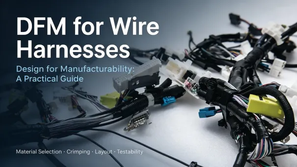
Many wire harness production challenges do not originate from electrical design errors. Instead, they arise when a design meets its functional requirements but does not adequately account for practical manufacturing constraints, including assembly, crimping, molding, final testing, and material availability. A design that appears feasible on a drawing may create problems on the production line, such as terminals that are difficult to insert into connector housings, interfering harness branches, insufficient assembly clearance, unnecessarily tight dimensional tolerances, or materials that are unsuitable for the actual operating environment.
When these issues are discovered during pilot production, they can lead to additional rework, scrap, and delivery delays. Design for Manufacturability (DFM) addresses these challenges by incorporating manufacturing, process engineering, quality, and procurement considerations early in New Product Introduction (NPI). The objective is to make wire harnesses easier to manufacture consistently, optimize total cost, and maintain product quality and reliability without compromising required performance.
DFM is not simply about simplifying a design or reducing specifications. It is a cross-functional engineering review process that spans concept development, schematics, bills of materials (BOMs), 2D and 3D drawings, prototype validation, and pilot production release. As an important part of the Design for X (DFX) methodology, DFM can be used alongside Design for Assembly (DFA) and Design for Testability (DFT).
For automotive, solar, marine, medical, and industrial automation applications, wire harness DFM reviews should consider customer drawings, connector and terminal manufacturer specifications, applicable industry standards, manufacturing capabilities, and quality control plans. Standards such as IPC/WHMA-A-620 can provide relevant workmanship and acceptance criteria, but they do not replace a comprehensive DFM review.
DFM vs. DFA vs. DFT: What Is the Difference?
DFM, DFA, and DFT are related engineering approaches, but each focuses on a different aspect of product development.
Design for Manufacturability (DFM): Focuses on making a product easier and more consistent to manufacture using available materials, processes, equipment, and production capabilities. For wire harnesses, this includes wire and terminal compatibility, crimping process feasibility, material availability, and dimensional tolerances.
Design for Assembly (DFA): Focuses on simplifying assembly operations, reducing handling complexity, and preventing assembly errors. For wire harnesses, this includes connector accessibility, terminal insertion direction, branch routing, fastening methods, and sufficient space for taping and installation.
Design for Testability (DFT): Focuses on making a product easier to inspect and test, with suitable test access and coverage. For wire harnesses, this includes accessible test points, continuity and pin-mapping verification, suitable electrical test fixtures, and protection of sensitive electronic components during testing.
These approaches overlap and should be considered together. For example, changing a connector may improve material availability (DFM), simplify terminal insertion (DFA), and make electrical testing easier (DFT). The final design should balance manufacturing feasibility, assembly efficiency, and test coverage while meeting the product's functional and quality requirements.
1. DFM Fundamentals: How Design Decisions Affect Lifecycle Cost and Manufacturability
Design decisions influence material costs, manufacturing labor, quality control, and maintenance requirements throughout a product's lifecycle. As a project progresses from prototyping to pilot production and mass production, design changes may also require tooling adjustments, inventory management, revalidation, and production schedule changes.
Conducting DFM reviews early helps identify and address manufacturability issues before they become more expensive to resolve.
A traditional development process often follows a sequential path: design release, prototyping, pilot production, problem identification, and engineering change. DFM encourages a concurrent engineering approach in which process engineers, quality engineers, procurement specialists, and test engineers participate during the design phase.
Key review questions include:
-
Are the selected wires, connectors, protective sleeves, and auxiliary materials approved for the project, and do their lead times and minimum order quantities align with forecast demand?
-
Do the proposed crimping, wire stripping, ultrasonic welding, or soldering processes have a suitable process window to consistently meet applicable cross-section and pull-force requirements?
-
Are the harness branch layout, cable routing, and assembly sequence compatible with fixtures, workstations, and available operator access?
-
Can the production team consistently achieve the specified cable-length tolerances, shielding and grounding requirements, strain relief features, and labeling requirements?
-
Is there a feasible test strategy for the finished assembly, and can the required test fixtures and equipment be implemented?
2. Key DFM Review Areas for Wire Harnesses
2.1 Material Selection: Prioritize Proven and Traceable Approved Materials
Material selection is a starting point for wire harness DFM. Projects that rely heavily on custom connectors or specialized wire specifications may face long lead times, high minimum order quantities (MOQs), limited spare-part availability, and few qualified alternatives.
Where electrical performance, environmental resistance, regulatory requirements, and customer approval requirements can be met, mature, supply-stable, and traceable standard materials should be considered first. For custom components or single-source materials, the review should also assess lead times, MOQs, alternative sourcing options, and the cost of validating material changes.
Material selection must reflect the actual operating environment. For example, protective tubing used in high-temperature areas must have an appropriate temperature rating, while harnesses exposed to vibration may require suitable strain relief and retention features. Outdoor solar applications may require evaluation of UV exposure, moisture, and other environmental conditions.
Selecting materials based only on ordinary ambient conditions can increase the risk of insulation degradation, cracking, terminal back-out, and other field problems.
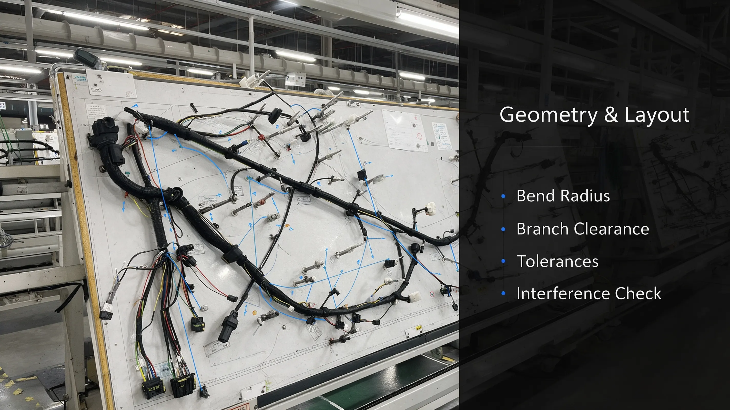
2.2 Geometry and Layout: Branching, Length, Bend Radius, and Assembly Access
A wire harness is more than a collection of connected wires. Branch routing and geometry directly affect fixture layout, assembly accessibility, and production efficiency.
Key DFM review points include:
-
Bend radius and strain relief: Follow the cable manufacturer's minimum bend-radius requirements and distinguish between fixed installations and applications involving continuous movement. For harnesses exposed to repeated flexing or vibration, evaluate dynamic bending capability, support-point locations, strain relief, and potential interference with surrounding components. These considerations help reduce localized stress and the risk of conductor or insulation damage.
-
Branch clearance and assembly access: Provide sufficient space for terminal insertion, taping, fastening, and other assembly operations. Restricted access can make assembly more difficult and increase the risk of handling errors.
-
Dimensional tolerances: Applying unnecessarily tight tolerances to every dimension can increase manufacturing difficulty, inspection costs, and the risk of nonconformance. Tolerances should reflect functional requirements, assembly datums, measurement methods, and actual process capability. Particular attention should be given to dimensions that affect installation, mating, and electrical connections.
-
Interference checks: Use 3D models, where available, to evaluate harness interference, compression, abrasion, and clearance risks in the fully assembled product or equipment. Reviewing the harness drawing in isolation may not reveal problems that arise during installation.
2.3 Termination Process DFM: Crimping, Soldering, and Shield Grounding
Crimping is a critical connection process in wire harness manufacturing. DFM reviews should confirm that the wire gauge, conductor construction, and terminal specifications are compatible. They should also verify that the crimping equipment, applicators, process parameters, and inspection methods can meet the applicable requirements.
Crimp acceptance criteria should be established using the relevant IPC/WHMA-A-620 requirements, terminal manufacturer specifications, customer requirements, and validated process parameters. Product acceptance class should be selected according to the application and customer requirements. The class alone does not determine every crimp dimension or pull-force limit.
Soldering and ultrasonic welding should also be evaluated where applicable. Considerations include joint accessibility, heat management, process control, and flux-residue management where soldering is used.
For shielded harnesses, the review should address shield termination methods, termination length, grounding terminal selection, and process accessibility. A shielding design that cannot be reproduced consistently on the production line may compromise electromagnetic compatibility (EMC) performance. The proposed termination method should therefore be practical to assemble and suitable for the intended EMC requirements.
2.4 Documentation and Drawing Requirements: Drawings, BOMs, Process Specifications, and Labels
Incomplete or ambiguous engineering documentation can create manufacturability problems even when the underlying design is technically sound.
A DFM review should verify that the engineering documentation is complete and consistent, including:
-
BOM part numbers, material codes, plating specifications, and wire colors
-
2D harness drawings, branch dimensions, routing information, and wrapping requirements
-
Label content, placement, and environmental durability requirements
-
Electrical test specifications, including applicable dielectric withstand and insulation resistance requirements
Vague instructions such as "follow industry standards" or "apply suitable wrapping" can lead to different interpretations across operators, production teams, and manufacturing batches.
Where requirements affect product acceptance, drawings and supporting documents should identify the applicable specifications, dimensions, materials, and workmanship criteria clearly enough for consistent implementation and inspection.
2.5 Testing and Inspection DFM (DFT)
Design for Testability (DFT) should be considered alongside DFM to ensure that the proposed assembly can be tested effectively.
The review should establish a feasible test strategy covering continuity and pin mapping, insulation resistance or dielectric withstand testing where required, and any necessary functional tests.
For assemblies with inaccessible test points, complex branches, or sensitive electronic components, evaluate fixture design, test paths, test coverage, and the risk of damaging components during testing. Test methods and inspection frequency should be determined by product specifications, customer requirements, and risk assessment.
3. Implementing DFM Throughout NPI
DFM should be integrated into the NPI process rather than treated as a one-time review.
-
Initial DFM review during concept development: Conduct a preliminary material and process feasibility assessment. Estimate costs, identify manufacturing risks, and evaluate high-risk design options before detailed development.
-
Cross-functional DFM review before design release: Review drawings and BOMs with the relevant engineering, quality, procurement, and manufacturing teams. Record identified issues and assign priorities. Companies may define internal categories such as P0, P1, and P2. For example, issues affecting safety, regulatory compliance, or critical functionality may be designated as release blockers. The classification rules should be defined by the organization's project management and quality systems.
-
Prototype validation: Build prototype units to evaluate assembly operations, terminations, and material compatibility. Record manufacturing feedback and update the DFM issue list.
-
Pilot production review: During pilot production, analyze labor time, scrap, rework, and defect patterns. Use the findings to refine drawings, tooling, and work instructions where necessary.
-
Production release and continuous improvement: Collect relevant process-monitoring data, production defects, rework records, customer complaints, and failure analysis results. Feed verified findings into future DFM checklists and process specifications.
4. Common DFM Misconceptions
DFM is only about reducing cost. Incorrect. DFM balances performance, reliability, cost, and manufacturability. Manufacturing convenience must not come at the expense of required functionality, ingress protection, or safety.
DFM only requires drawing review. Incorrect. Effective DFM involves cross-functional input from design, process engineering, quality, procurement, and manufacturing.
DFM is complete after one review. Incorrect. DFM should evolve as new information becomes available. Verified findings from prototype builds, pilot production, and mass production should inform future projects.
Every dimension should have the same tight tolerance. Incorrect. Tolerance requirements should reflect functional needs and manufacturing capability. Critical dimensions may require tighter control, while less critical dimensions can use tolerances that remain compatible with assembly and product performance.
5. Benefits of Wire Harness DFM
A structured wire harness DFM process can support measurable improvements, depending on the project and the effectiveness of implementation. Potential benefits include shorter NPI cycles, fewer design changes during pilot production, reduced scrap and rework, lower assembly labor requirements, more consistent crimping and assembly quality, fewer field issues, and improved material sourcing flexibility.
Effective DFM reviews identify potential problems with materials, terminations, routing, assembly, and testing before drawings are released. Prototype validation and pilot production feedback are then used to confirm corrective actions.
Review outcomes should be reflected in engineering drawings, BOMs, process documents, and inspection plans so that design requirements can be implemented consistently on the production floor.
Conclusion
For wire harness projects, DFM connects design decisions with the practical requirements of manufacturing, inspection, and production release. By reviewing material selection, termination processes, harness geometry, documentation, and testability early in development, engineering teams can identify potential issues before they lead to costly changes.
A useful DFM process does not end with a review meeting. It links identified risks to documented corrective actions, prototype validation, and pilot production results. This approach helps OEMs and wire harness manufacturers improve production readiness, manage manufacturing costs, and maintain consistent product quality.