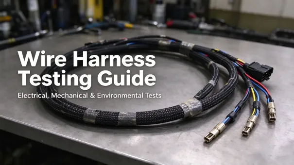
Wire harness failures rarely manifest immediately after delivery. Many field issues originate from hidden crimp defects, insulation damage, incorrect wiring, or connector sealing weaknesses that simple visual checks can miss. For OEMs working in automotive, industrial machinery, marine, robotics and battery systems, a properly scoped wire harness testing strategy is essential to reduce safety risk and keep performance consistent.
This guide outlines the test workflow for custom wire harness assemblies and separates production end-of-line tests, process validation tests, and design qualification tests. It references widely used industry standards so OEM buyers can specify realistic test coverage for their projects and understand the limits of each method.
Visual & Dimensional Inspection
Visual inspection is a key part of wire harness quality control. Inspection points and frequency should be defined by the product specification and control plan, since not every assembly is checked in the same way before electrical testing.
-
Stripping length, conductor strand integrity, no nicked copper
-
Crimp geometry: crimp height, barrel closure, no over-crimp or under-crimp
-
Connector pin seating: fully locked terminals, no back-out, correct cavity placement
-
Insulation, tubing, tape routing, strain relief, cable length tolerance
-
Seal installation for IP-rated connectors and correct gasket orientation
Visual inspection is one part of the overall acceptance process. It should be combined with the electrical and other tests required by the product specification and control plan.
Electrical Testing
Electrical tests verify circuit integrity and insulation isolation. For critical harness assemblies, 100% end-of-line electrical testing is commonly specified to verify circuit mapping and detect assembly defects. Insulation resistance and dielectric withstand testing should be performed when required by the product specification, customer requirements, or applicable safety standards, using test conditions compatible with the assembly. Harnesses that incorporate electronic components, surge protection devices, or sensors require special evaluation of test voltages and wiring methods, since test voltages can damage sensitive parts.
Test voltage and acceptance limits are project-specific. Confirm them against the product specification, customer requirements and applicable standards before production; do not apply a fixed voltage or resistance value across all harness types.

Continuity & Resistance Testing
Continuity testing verifies the specified circuit connections and detects opens, shorts, and incorrect pin assignments. Where resistance limits are required, establish them from the conductor specifications, circuit length, terminal interfaces, measurement method, and customer requirements. Four-wire Kelvin measurement may be appropriate when accurate low-resistance measurements are required.
Checks: open wires, missing terminals, wrong pin assignment, and elevated-resistance crimp interfaces.
Insulation Resistance (IR) Test
Insulation resistance testing applies a specified DC voltage between conductors or between a conductor and a defined reference point. The measured resistance is compared with the acceptance criteria in the product specification or applicable test standard. Low readings may indicate insulation damage, contamination, moisture ingress, or unintended conductive paths, but further investigation may be needed to identify the cause.
Dielectric Withstanding Voltage (Hi-Pot / DWV) Test
Dielectric withstand testing checks whether the insulation system can tolerate the specified test voltage without breakdown or unacceptable leakage under defined test conditions. It complements continuity and insulation resistance testing but does not identify every physical defect in the insulation.
Test voltage, duration, leakage limits and test connections should follow the applicable specification. Assemblies containing electronic components or other voltage-sensitive devices require particular care when selecting the test method and conditions.
Voltage Drop Test
Voltage drop testing measures the voltage lost across a circuit or specified connection under a defined load. Results can help identify excessive circuit resistance caused by factors such as poor termination quality, undersized conductors, or unsuitable connection interfaces. Test current, measurement points and acceptance limits should be specified for the application.
Mechanical Testing (Process Validation, Sampling)
Mechanical tests validate termination strength and connector retention. Most are sampling-based process validation activities rather than checks performed on every finished unit. They are used for first article validation, tooling qualification, periodic process checks and material change control.
Crimp Pull Force Test
Pull force testing applies controlled tension to a crimped termination to evaluate its mechanical strength. Minimum acceptance values depend on the wire size, terminal design, applicable requirements and project specifications. Results outside the acceptance limits may indicate incorrect crimp settings, incompatible wire-terminal combinations, conductor damage or other process issues. Failed results should be investigated and handled according to the control plan and nonconformance procedure.
Crimp Cross-Section Microsection Analysis
Crimp cross-section analysis can be used during process development, tooling qualification, or failure investigation to evaluate conductor compression and terminal deformation. Acceptance criteria and inspection frequency should follow the terminal manufacturer's requirements, customer specifications, and the applicable validation plan.
Connector Insertion & Retention Force
These tests verify that terminals remain seated in the connector housing and that mating or unmating forces meet the specified requirements, helping to prevent terminal back-out and mating difficulties during OEM assembly.
Leak / Bubble Test for Sealed Assemblies
Leak testing may be used to screen sealed connector or harness assemblies when a validated method is available. Test pressure, allowable leakage, fixture configuration and acceptance limits must be defined for the specific design. Formal IP-rating claims require verification using the applicable test method and the specified test conditions.
Environmental Qualification Testing (Design Validation)
The test sequence, severity levels, duration and acceptance criteria should be defined by the application requirements, applicable standards and validation plan. Not every harness requires every test listed below. Environmental qualification evaluates whether the harness meets specified performance requirements under defined environmental conditions, typically on sampled units for new product validation, design or material changes, or customer request.
-
Thermal cycling: extreme high / low temperature dwells and transition cycles
-
Temperature & humidity cycling
-
Vibration & mechanical shock (automotive / military)
-
Salt spray testing (NSS or AASS, where specified) to evaluate corrosion resistance
-
Water ingress testing for IP rating validation
-
Thermal ageing to assess long-term insulation performance
Depending on the validation plan, post-test inspections and electrical checks may be required to verify that the harness continues to meet specified requirements after environmental exposure.
Test Matrix
|
Test category
|
Typical purpose
|
Typical frequency
|
|---|---|---|
|
Visual and dimensional inspection
|
Check assembly, cosmetic and dimensional features
|
As defined by control plan
|
|
Continuity and pin mapping
|
Detect opens, shorts and miswired circuits
|
Usually performed on every unit
|
|
Resistance / voltage drop
|
Verify defined electrical performance under load
|
Determined by product requirements
|
|
Insulation resistance
|
Verify insulation integrity
|
Defined by product specification and test plan
|
|
Hi-pot / dielectric withstand
|
Verify insulation system voltage endurance
|
Per applicable specification and safety requirements
|
|
Crimp pull force
|
Validate mechanical strength of crimp terminations
|
Process validation and sampling plan
|
|
Crimp cross-section
|
Evaluate crimp internal structure
|
Validation plan or failure investigation
|
|
Environmental qualification
|
Verify performance under defined environmental conditions
|
New product validation, design change or customer request
|
The frequencies shown reflect general engineering practice and are not universal requirements for every customer project.
Industry Standards Reference
Test programmes can be tailored to product requirements with reference to these widely used specifications:
-
IPC/WHMA-A-620: requirements and acceptance criteria for cable and wire harness assemblies, covering manufacturing workmanship and interconnection acceptance. It does not mandate universal inspection frequencies or electrical test limits for all projects.
-
USCAR-21: performance requirements for automotive crimped electrical connections; the applicable scope depends on the version and clauses specified by the customer.
-
ISO 20653: road vehicle degrees of protection (IP codes) for electrical equipment enclosures and associated test methods.
-
IEC 60512: test methods for electrical connectors, not a complete standard for full wire harness assemblies.
Additional industry-specific, regulatory, and customer requirements may apply to military, medical, marine, and other specialized applications. The applicable requirements should be confirmed during project definition.
Production Test Records
Test records support traceability and continuous improvement. They should capture the information required by the customer's traceability requirements and the factory quality system, which may include:
-
Product part number, revision and lot or serial number
-
Test procedure or specification version used
-
Test results and nonconformance disposition
-
Test equipment identification, calibration status and test date where applicable
Best Practices for OEM Buyers
-
Define test requirements in your drawing and statement of work before production starts; do not rely on assumed default coverage.
-
Separate end-of-line production checks, process validation sampling and design qualification testing.
-
Establish traceability for critical assemblies, linking serial numbers to test records as required.
-
Complete first article inspection and test review before mass production release.
-
Revalidate test plans whenever wiring, connectors, tooling or raw materials change.
Conclusion
A robust wire harness testing programme combines visual inspection, end-of-line electrical testing, and process and design qualification. Each method has a defined scope and limitation: visual inspection identifies obvious assembly defects, end-of-line electrical testing helps verify circuit integrity and detect specified wiring faults before shipment, and process and design qualification validate that the assembly meets performance requirements under defined mechanical and environmental conditions. A suitable test plan should be aligned with the application risk level and customer specifications rather than applied uniformly across all projects.
FAQ
Can I skip Hi-Pot if continuity passes?
Continuity testing verifies circuit connections but does not establish whether the insulation can withstand the specified operating or test voltage. Where required by the product specification or applicable safety standards, Hi-Pot testing provides a separate check of dielectric withstand performance.
Is pull force testing performed on every finished harness?
No. Pull force is a destructive process validation test used for sampling rather than 100% final inspection.
What test is best for verifying IP68 waterproof harnesses?
Leak testing can be used to screen sealed assemblies when the method has been validated for the design. An IP68 claim requires verification against the applicable IP test requirements, including the specified immersion conditions and acceptance criteria. The test conditions should be defined for the complete assembly or enclosure being rated.