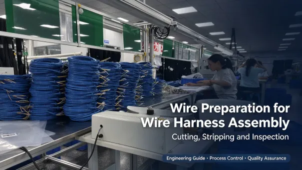
Wire Preparation for Wire Harness Assembly: Cutting, Stripping and Inspection
A practical engineering reference for wire cut-length control, insulation stripping, conductor-end inspection, and the quality checks that support reliable crimped and soldered connections. Acceptance criteria should be verified against the applicable IPC/WHMA-A-620 revision, terminal application specifications, and customer drawings.
1. What Is Wire Preparation and Why It Matters
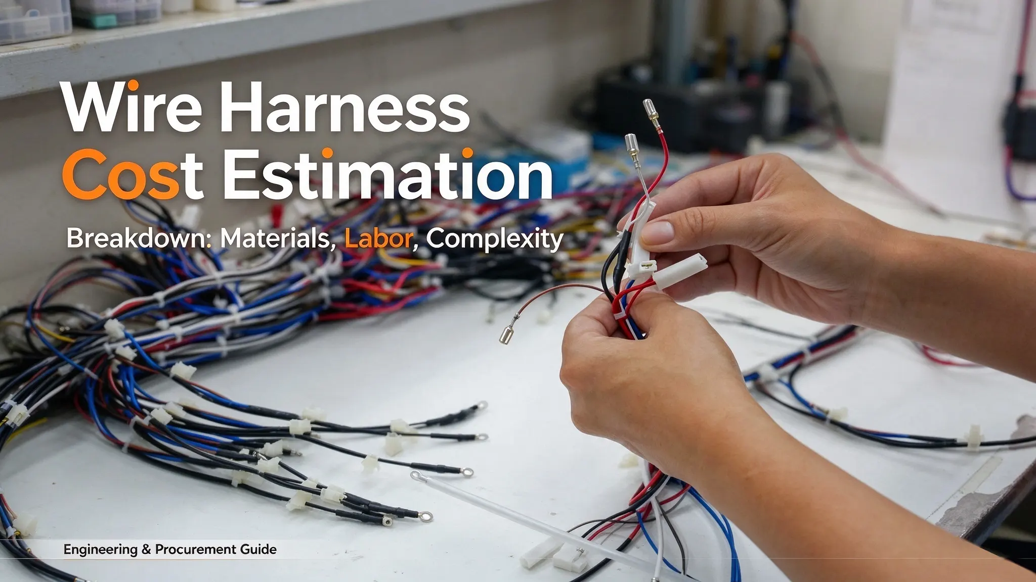
Wire preparation is the upstream process that converts bulk wire from a reel into cut-to-length, stripped conductor ends ready for terminal crimping, soldering, or connector insertion. It includes three core operations: cutting to length, insulation stripping, and conductor end conditioning (light twisting, brushing, or tinning where specified by the drawing).
Although wire preparation is only the first station in harness manufacturing, it directly affects the mechanical and electrical reliability of every downstream joint. IPC/WHMA-A-620 establishes workmanship and acceptance requirements for cable and wire harness assemblies, including conductor preparation and termination-related processes; applicable criteria should always be verified against the revision specified by the customer.
Critical principle: A crimp or solder joint is only as strong as the conductor it captures. Damaged strands, incorrect strip length, and insulation damage must be identified before termination. Once the conductor has been damaged during preparation, downstream processing cannot restore its original condition.
2. Wire Preparation Process Flow
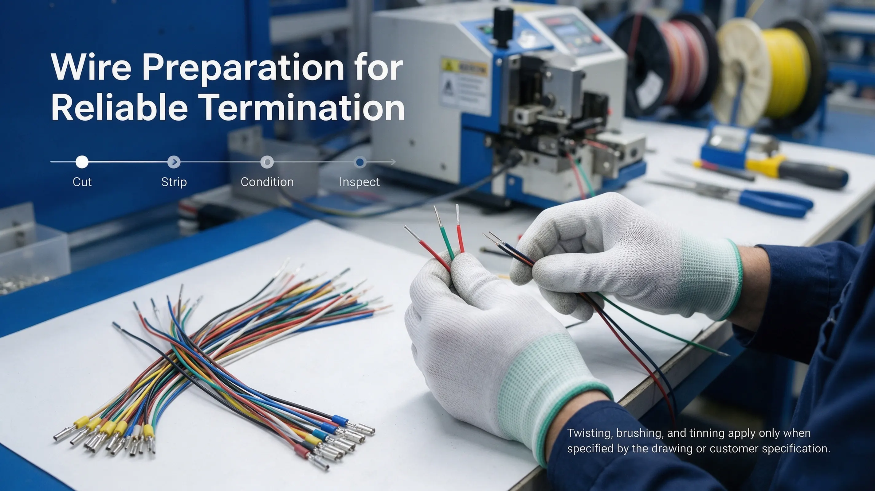
The standard sequence from raw reel to ready-to-crimp wire is shown below. Not every step applies to every project — twisting, brushing, and tinning are conditional operations called out only on specific drawings or customer specifications.
3. Step-by-Step Process
3.1 Cutting to Length
The first operation feeds wire from the reel through a straightener and cuts it to the specified branch length. Length accuracy directly affects harness fit on the assembly fixture and in the vehicle or end equipment.
Key parameters:
- Cut-length tolerance is defined by the product drawing or customer specification. As a reference, many automotive drawings use ±5 mm on short branches and ±10 mm on long runs — project-specific, not a universal IPC requirement.
- Cut end should be reasonably square to the conductor axis so that all strands seat fully in the crimp barrel.
- De-reeling tension must avoid conductor necking or insulation deformation while preventing tangling.
Equipment: Manual cutters for low volume; semi-automatic cut-strip machines for medium volume; fully automatic cut-and-strip lines (e.g., Komax, Schleuniger) for high-volume production, with integrated length verification when required by the process plan.
3.2 Insulation Stripping
Stripping removes a precise length of insulation from the wire end to expose the conductor for termination. The strip length is dictated by the terminal or splice application specification — it is not chosen freely by wire size alone.
Illustrative strip length ranges (for initial reference only):
The table below gives typical starting ranges for planning only — not universal acceptance values. Confirm the final strip length from the terminal manufacturer's application drawing and customer harness drawing; it depends on crimp barrel geometry, insulation crimp design, strand construction, and the required conductor brush (exposed conductor beyond the insulation crimp).
|
Wire Size (mm²)
|
Illustrative Strip Range
|
Typical Application
|
Where to Confirm Final Value
|
|---|---|---|---|
|
0.35 – 1.0 mm²
|
~2.0 – 3.0 mm
|
Open-barrel signal terminals
|
Terminal application drawing / crimp spec
|
|
1.0 – 2.5 mm²
|
~3.0 – 4.5 mm
|
Power / signal sealed terminals
|
Terminal application drawing / crimp spec
|
|
4.0 – 6.0 mm²
|
~4.5 – 5.5 mm
|
Battery / main power cables
|
Terminal application drawing / lug spec
|
|
10.0 mm² and above
|
~6.0 – 8.0 mm
|
Heavy-power lugs / busbar
|
Lug / terminal manufacturer spec
|
Stripping methods:
- Mechanical (blade) stripping: Two or four blades score the insulation and pull it off. Most common; requires regular blade inspection and replacement.
- Thermal stripping: Uses controlled heat to remove insulation and may be suitable for selected wire constructions and insulation materials (e.g., PTFE, silicone) that splinter under mechanical blades. Process parameters — temperature and contact time — must be validated for the specific wire to avoid insulation residue, conductor damage, or undesirable changes in material properties.
- Laser stripping: Precision ablation for micro-wires and aerospace applications. Minimal strand damage, but higher equipment cost.
3.3 Conductor End Conditioning
After stripping, the exposed strands may need conditioning before termination.
3.3.1 Twisting
Stranded conductors can splay during stripping. Light re-twisting may be used to bring strands back together, provided it does not alter the original conductor lay or work-harden the strands. After any permitted re-twisting, the conductor should retain its original strand lay without excessive deformation or loose strands that could interfere with termination.
3.3.2 Brushing
Brushing to align strands and remove stray strands is used only when the process, conductor construction, and terminal application specification call for it. It is not a default step for every fine-strand wire, and an overly aggressive brush can damage strands or alter the conductor lay.
3.3.3 Birdcaging (Defect)
Birdcaging is the outward splaying of strands caused by incorrect stripping blade clearance, excessive pulling force, or dull blades. It prevents the strands from seating uniformly in the crimp barrel and degrades crimp consistency and pull-out performance. Prevention requires correct blade gauge selection, correct machine settings, and regular blade inspection.
3.4 Tinning (Conditional Operation)
Tinning — pre-soldering the stripped conductor end — should be performed only when required by the specified termination process or customer requirements. Its suitability must be confirmed for the conductor, terminal, and joining method. Modern automotive crimped connections are generally validated on bare (untinned) copper conductors, and tinning is not a default requirement for routine crimped harnesses: it stiffens the conductor and can introduce brittle intermetallic layers. Always follow the drawing and the terminal/crimp application specification to decide whether tinning applies to a given joint.
4. Critical Preparation Defects and How to Judge Them
The table below lists the most common wire preparation defects, their typical causes, how they are inspected, and the basis on which acceptance should be judged. The acceptance basis refers to the applicable IPC/WHMA-A-620 revision, the terminal application specification, and the customer drawing — not to generic numeric limits invented here.
|
Defect
|
Typical Cause
|
Inspection Method
|
Acceptance Basis
|
|---|---|---|---|
|
Strand nicking or severance
|
Incorrect blade depth, wrong blade gauge, worn blades
|
Magnified visual inspection; cross-section on first article / sample
|
Applicable IPC/WHMA-A-620 criteria and customer specification
|
|
Birdcaging (strand splaying)
|
Incorrect stripping settings, excessive pulling force, dull blades
|
Visual inspection of stripped end
|
Applicable workmanship criteria; strands must seat uniformly in barrel
|
|
Insulation nicking or scoring at the strip shoulder
|
Blade set too deep, strip-length setpoint error
|
Visual and dimensional check
|
Wire specification and customer requirements; insulation integrity must be maintained
|
|
Over-strip (conductor too long)
|
Strip-length setpoint error
|
Length measurement against terminal drawing
|
Terminal application drawing
|
|
Under-strip (insulation enters crimp barrel)
|
Strip-length setpoint error
|
Length measurement; crimp cross-section if needed
|
Terminal application drawing — insulation must not enter the conductor crimp zone
|
|
Angular / irregular cut end
|
Dull cutter blade, wire not seated against stop
|
Visual inspection
|
Process requirement set to ensure full strand capture in the barrel
|
|
Insulation deformation or compression
|
Excessive feed tension, die pressure too high
|
Visual and dimensional check
|
Wire specification; insulation wall thickness and flexibility must remain within design limits
|
5. Equipment Selection Guide
|
Production Volume
|
Typical Equipment Class
|
Production Considerations
|
|---|---|---|
|
Prototype / low volume
|
Manual wire cutters + hand strippers
|
Low investment; accuracy depends on operator skill; suitable for R&D and one-off assemblies
|
|
Medium volume
|
Semi-automatic cut-strip machine
|
Repeatable setups; strip length and cut length programmed; verify actual capability before release
|
|
High volume
|
Fully automatic cut-strip + crimp machine
|
High repeatability; supports in-process monitoring and lot traceability; vendor-specified accuracy must be confirmed by a process capability study on the actual wires and terminals
|
6. In-Process Quality Control
Wire preparation checks verify cut length, strip length, and conductor condition. Crimping checks verify the quality of the completed terminal connection.
6.1 Wire Preparation Controls
- First-article inspection at setup — after machine setup, wire change, or blade change: measure cut length and strip length against the drawing / terminal spec; inspect the stripped end under magnification for strand nicking, birdcaging, and insulation damage; cross-section a sample if required by the quality plan.
- Routine in-process checks — periodic verification of cut length, strip length, and stripped-end appearance, on a frequency defined by risk, process capability, and customer requirements. IPC/WHMA-A-620 does not prescribe a single universal inspection frequency; it is set by the responsible quality system.
- Blade and tooling condition — inspect blades regularly for wear or nicks, and follow the equipment / blade manufacturer's recommended replacement interval. Adjust the interval based on observed defect trends rather than relying on a fixed cycle count.
6.2 Crimping Process Controls (Downstream)
- Crimp height monitoring — measured at defined intervals and trended; this is a crimp-setting parameter, not a preparation parameter.
- Pull-out force testing — destructive sampling per the applicable specification (e.g., SAE/USCAR-21 for automotive uninsulated crimps). A pull-out result reflects the combined condition of the terminal, crimp tooling, wire preparation, and crimp height — investigate systematically rather than assuming preparation is the cause.
- Crimp cross-section analysis — on first article and at defined intervals, with acceptance judged against the terminal application specification and applicable crimp standard — typically verifying deformation and strand containment; specific void criteria, where applicable, are defined by those documents rather than by a universal rule.
7. Applicable Standards and How They Apply
|
Standard
|
Reasonable Scope in This Article
|
|---|---|
|
IPC/WHMA-A-620
|
Workmanship and acceptance requirements for cable and wire harness assemblies, including conductor preparation, stripping, strand condition, and termination-related appearance. Always reference the revision specified by the customer; revision history is published by IPC.
|
|
SAE/USCAR-21
|
Performance specification for unstaked / uninsulated terminal crimp connections in automotive low-voltage electrical systems. It validates crimped connection performance (pull-out, cross-section, temperature cycling, etc.) — it is not a standalone wire cutting or stripping acceptance standard.
|
|
LV214 and similar OEM norms
|
Customer-specific automotive harness requirements. Apply only when the customer drawing or specification explicitly invokes them.
|
|
UL 486A-486B
|
Safety requirements for wire connectors and lugs and their pull-out test methods. Relevant only when the terminated product is within the certified scope; not a general wire-preparation workmanship standard.
|
8. Wire Preparation Process Validation in Production
Before production starts, verify the preparation settings against the product drawing and terminal application specification. The exact records and frequencies are defined by the customer and the internal quality system:
- Set up from the drawing. Load the cut length, strip length, and any required conductor-end treatment directly from the customer harness drawing and the terminal application specification — not from memory or a different project.
- Produce a first article. Run a small sample and measure cut length and strip length with calibrated tools; inspect the stripped end under magnification; cross-section a sample crimp if required.
- Record the setup. Log wire lot, machine settings, blade gauge, first-article measurements, and inspector identity for traceability.
- Re-validate on any change. Re-verify the affected preparation settings after changes to wire type, tooling, or machine parameters. The extent of revalidation should follow the control plan and customer requirements, with first-article approval where required.
- Contain on anomaly. If a defect trend appears, quarantine the affected lot, identify root cause, correct it, and re-run first-article verification before release.
9. Frequently Asked Questions
What strip length should I use for a 0.5 mm² wire with an open-barrel terminal?
Start from the terminal manufacturer's application drawing — strip length is defined by the terminal geometry, not by wire size alone. As a planning reference, 0.5 mm² signal wires commonly fall in the 2–3 mm range, but the production setpoint must come from the validated terminal specification and confirmed on first article.
Is one nicked strand acceptable?
It depends on the applicable IPC/WHMA-A-620 revision, the conductor type, and the customer's class / additional requirements. A micro-nick that does not sever a strand may be conditionally acceptable under some criteria, while a fully severed strand is not. Judge against the standard drawings and customer spec for the project; when in doubt, cut off the end and re-strip.
What is the difference between thermal and mechanical stripping?
Mechanical stripping scores and pulls the insulation off with blades — fast and economical, but sensitive to blade adjustment. Thermal stripping uses controlled heat and may be better suited to certain insulation materials that splinter mechanically, but the temperature and contact time must be validated for that specific wire to avoid residue or conductor property changes. Choose the method based on the wire's insulation type and the validated process.
10. Summary
Wire preparation is the upstream control that determines whether downstream crimped and soldered connections can perform as designed. Set cut length and strip length from the product drawing and terminal specification, keep the stripped conductor condition within the acceptance criteria of the applicable workmanship standard and customer requirements, and verify settings on first article and on any controlled change. Judge every result against the applicable IPC/WHMA-A-620 revision, the terminal application drawing, and the customer specification — not against generic numeric limits.