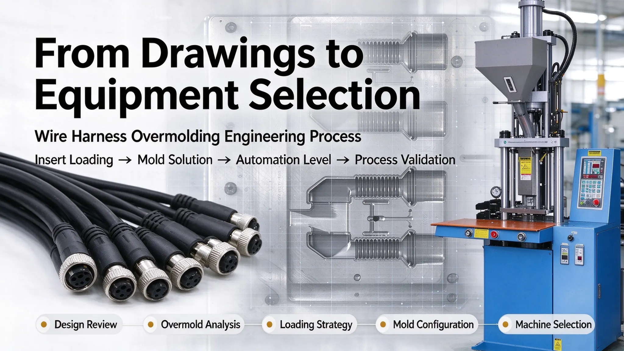
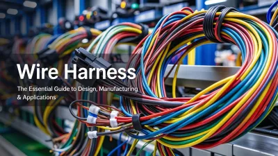
Wire harness overmolding safeguards cables, terminals, and connectors for automotive, medical, industrial, and consumer electronic products, delivering essential insulation, structural protection, and environmental sealing. Engineers frequently face the choice between vertical and horizontal injection molding setups for overmold projects, a decision that directly impacts mold feasibility, yield rate, and long-term production stability. Many manufacturing teams rely on outdated generalizations to pick machine types, which often leads to fixture mismatches, insert shifting, or inefficient cycle performance. Real-world machine selection takes insert shape, loading approach, mold structure, material behavior, and automation plans into account. This guide shares practical factory-tested judgment standards, common defect analysis, and structured project workflows to help engineers match the right injection molding configuration for each wire harness overmolding requirement.
What Is Overmolding in Wire Harness Manufacturing?
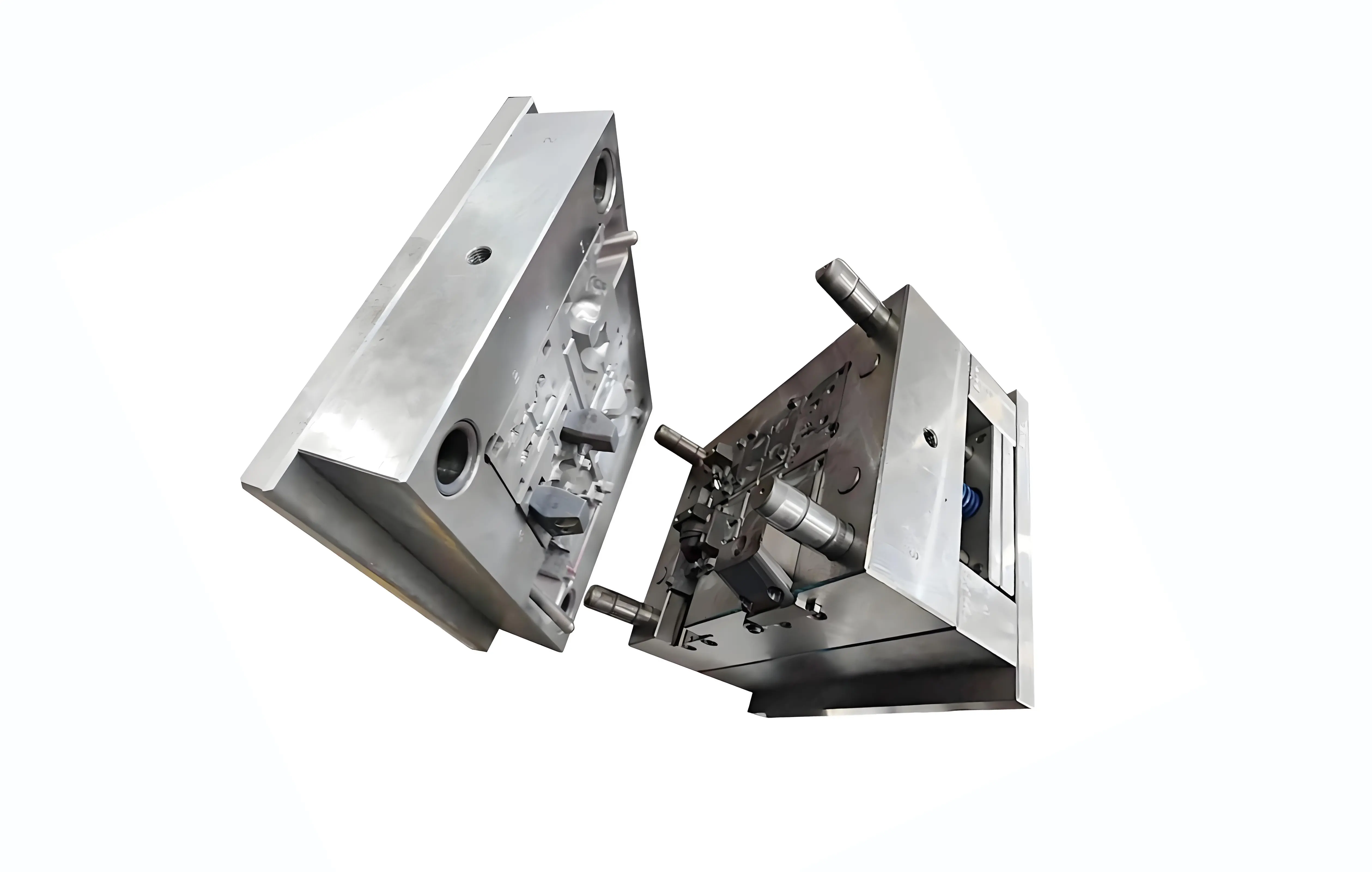
Wire harness overmolding (also defined as insert molding for cable assemblies) encapsulates pre-assembled cables, terminals, and connector inserts within thermoplastic or silicone polymer materials. The molded structure provides critical strain relief, environmental sealing, mechanical impact protection, and electrical insulation at wire termination and connection points.
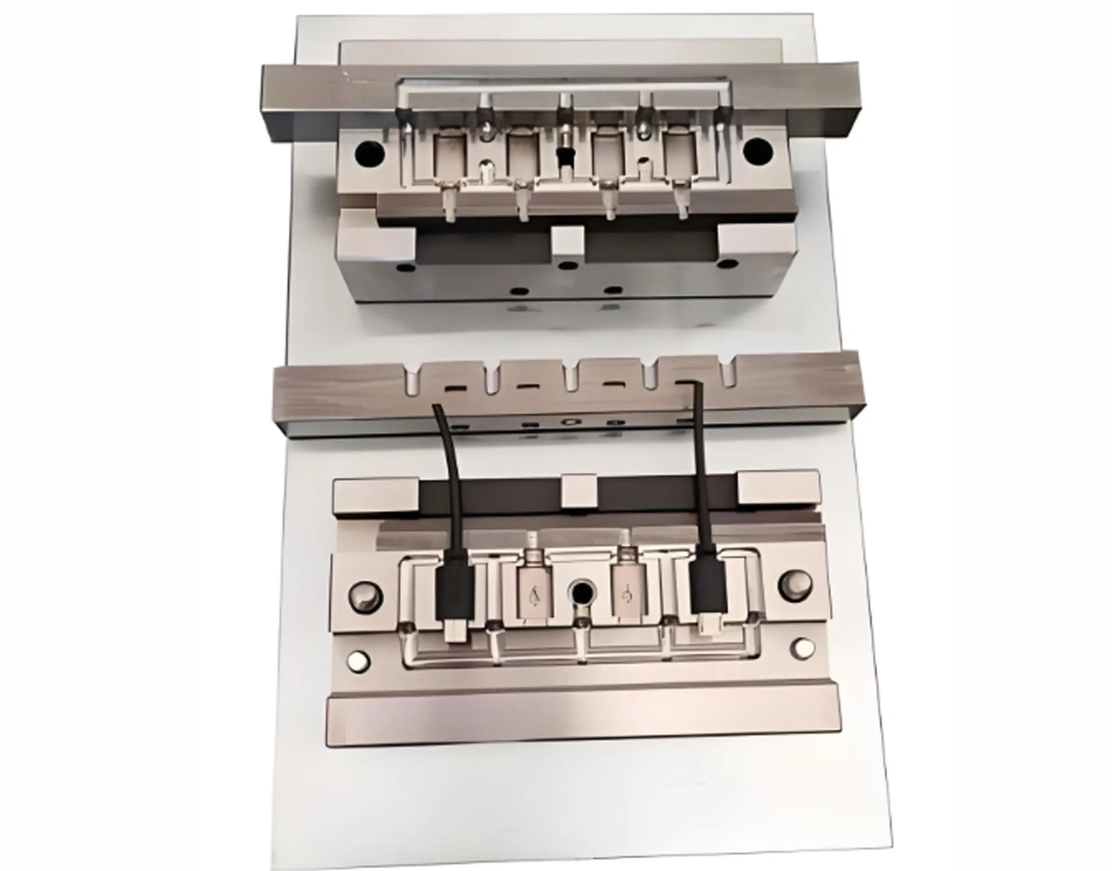
Unlike conventional plastic injection molding, harness overmolding must protect pre-formed, fragile cable and terminal inserts throughout filling, packing, and cooling. Conductor alignment, insulation integrity, shielding continuity, and terminal retention must remain stable during every molding cycle. For this reason, mold access, insert fixation method, and process controllability are critical design and selection factors for production success.
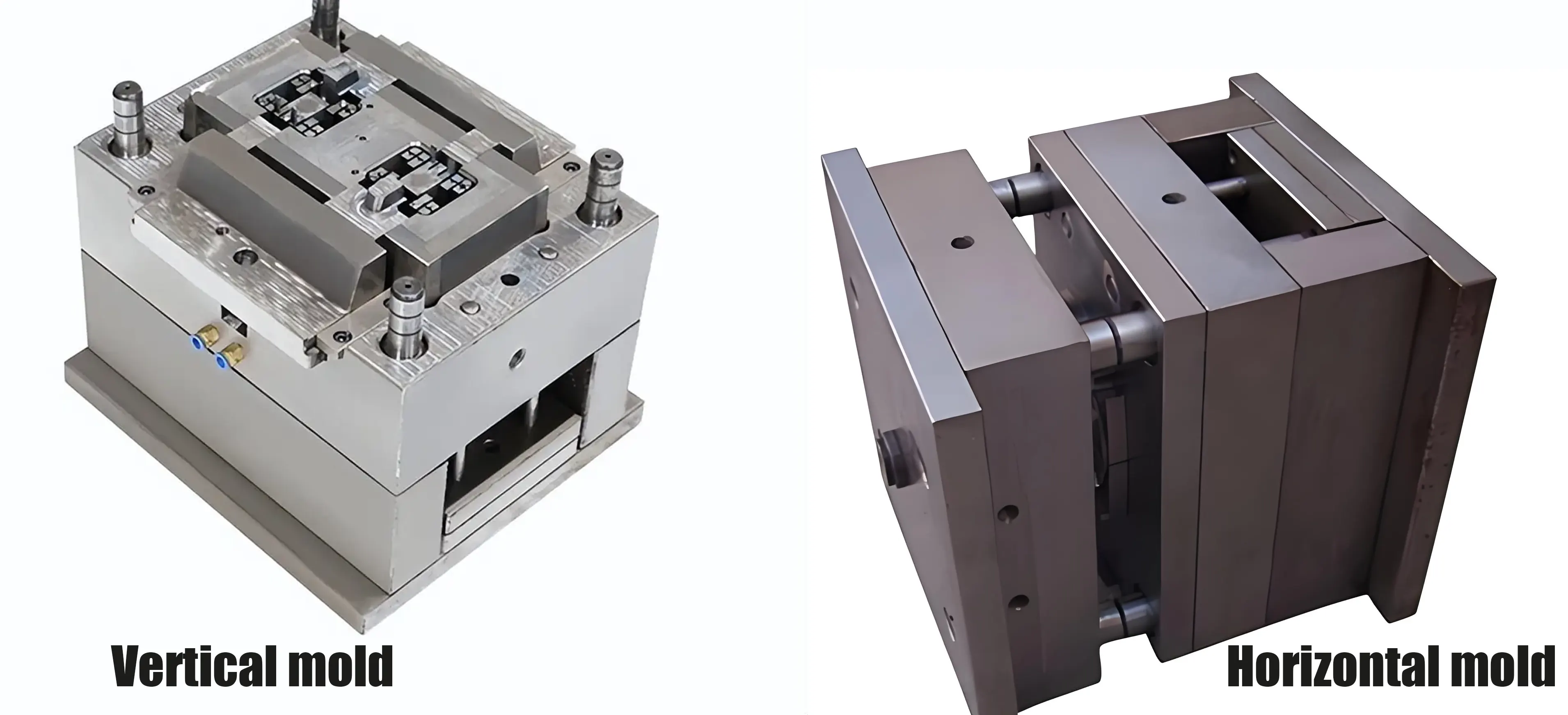
1. Vertical vs Horizontal Injection Molding: Core Structural Differences
1.1 Vertical Injection Molding Structure & Operational Characteristics
Vertical platforms commonly integrate rotary tables and multi-station sliding molds, enabling multi-position workflows that let operators prepare one set of inserts while another cavity is in production. This reduces idle machine time and improves overall output for mixed-part runs. Side-core mechanisms are also frequently deployed on vertical molds to form undercuts, lateral grooves, sealing features, and other geometries that cannot be released along the primary mold-opening direction. These mold adaptations resolve most structural molding challenges for custom-shaped overmolded cable parts.
1.2 Horizontal Injection Molding Structure & Operational Characteristics
Horizontal machines open along a horizontal axis, with part ejection handled by the machine’s built-in ejector system. This layout pairs naturally with multi-cavity tooling and robotic insert loading, making it ideal for standardized cable and terminal assemblies built in consistent batches. Flow length and filling behavior are governed by gate location, runner design, cavity geometry, insert configuration, and process tuning rather than machine orientation itself.
A key advantage of horizontal machines is seamless automation integration. The symmetric horizontal mold opening layout supports upstream insert feeding, robotic loading, automated part unloading, post-mold trimming, electrical testing, and vision inspection — forming a fully closed-loop production cell. This integrated workflow stabilizes cycle time, cuts manual labor reliance, and delivers consistent output for fixed-spec cable overmolding products.
2. Process Characteristics and Material Application Principles
PVC, TPU, TPE, PA and silicone can be processed on either machine configuration. The actual process window depends on melt temperature, viscosity, mold temperature, injection profile, venting and cooling requirements. Machine orientation does not inherently restrict material compatibility.
2.1 Vertical Machine Process Advantages
Vertical machines excel in flexible, high-mix production scenarios. Servo-driven injection systems support multi-stage velocity adjustment, suiting thin-wall and deep-cavity overmolding of
fine-gauge wires. Multi-zone barrel and mold temperature control improves melt uniformity, eliminating inconsistent material flow common with basic single-stage setups. Built-in low-pressure mold protection detects trapped inserts and foreign objects before mold closure, reducing mold collision risks and long-term maintenance costs.
2.2 Horizontal Machine Process Advantages
Horizontal machines are optimized for standardized batch production. Tuned injection speed reduces filling time, while precise mold temperature control and engineered cooling-channel layouts stabilize overall molding cycle performance for thermoplastic materials. Consistent part quality relies on coordinated tuning of back pressure, injection velocity, melt temperature, mold temperature, gate geometry, and venting, rather than adjustment of a single parameter.
Matched with robotic insert handling and multi-cavity tooling, horizontal systems can reduce manual labor dependence, stabilize cycle time consistency, and realize continuous batch production of standardized overmolded harnesses.
3. Typical Wire Harness Overmolding Applications & Process Considerations
The following application scenarios are common in actual production, but there is no fixed correspondence between industry/product and machine type. All scenarios support both vertical and horizontal equipment, and the final selection depends on production mode, automation level and mold configuration.
3.1 Flexible & Multi-Branched Harness Assemblies
Multi-branched signal harnesses and fine-gauge flexible cables for consumer electronics can be produced on both machine types. Vertical setups simplify manual insert handling and rapid mold swaps during custom small-batch runs. For large-batch standardized multi-branch harnesses, horizontal machines fitted with custom holding fixtures and robotic loading deliver stable, repeatable mass production.
3.2 Automotive High-Voltage Harness Assemblies
Automotive high-voltage harness overmolding demands reliable sealing and structural durability. Horizontal layouts work well for standardized terminal designs paired with robotic loading and multi-cavity tooling. For prototype or high-mix HV assemblies, either configuration can be used depending on insert complexity, fixture requirements and expected production volume.
3.3 Medical Cable Assemblies
Either machine configuration can be used for medical cable overmolding. The deciding factors are more often material compliance, cleanliness requirements, process validation, batch traceability, sterilization compatibility and insert handling logistics. A vertical setup may be convenient for manual loading during prototype or high-mix production, while an automated horizontal cell may be appropriate for stable high-volume production of standardized medical cable assemblies.
3.4 Industrial Cable & Drag Chain Assemblies
Industrial drag chain cables and equipment connection cables require consistent shielding integrity and mechanical durability. Standardized
industrial cable designs are well suited for horizontal automated batch production. Custom, low-volume, or special-shaped industrial harness prototypes are more flexibly produced on vertical machines with quick-change mold setups.
3.5 Connector & Terminal Overmolding
Terminal and connector overmolding is the most common cable overmolding process in mass production. Horizontal multi-cavity molds deliver efficient output for standardized power and signal terminals. Vertical rotary and slide mold bases support flexible mixed production for special-shaped terminals and low-batch custom connector designs.
4. Common Wire Harness Overmolding Defects and Possible Causes
Field defect resolution is core to overmolding process tuning. The table below lists frequent molding issues observed in wire harness production and their typical root causes, supporting targeted mold adjustment and process optimization:
|
Defect Type
|
Root Causes
|
|
Short shot
|
Insufficient shot volume, poor venting, incorrect melt or mold temperature, restricted gate geometry
|
|
Flash
|
Insufficient clamping force, excessive injection/packing pressure, worn or damaged parting surfaces, poor mold alignment, or excessive venting clearance
|
|
Wire displacement
|
Inadequate fixture retention, unbalanced injection force, poorly located gates, unsupported free cable length
|
|
Voids
|
Trapped air, insufficient packing, poor venting, material moisture, uneven cooling
|
|
Sink marks
|
Insufficient packing pressure/time, excessive local wall thickness, inadequate cooling, or poor gate/packing design
|
|
Burn marks
|
Compressed trapped air, excessive injection speed, poor venting
|
|
Delamination
|
Material incompatibility, contamination, poor surface condition, insufficient mechanical interlock, or inadequate bonding between the overmold material and cable/terminal surface
|
|
Cable insulation damage
|
Excessive melt temperature, high injection pressure, sharp mold edges, over-clamping
|
|
Low pull / peel strength
|
Insufficient mechanical anchoring or strain-relief geometry, poor material adhesion, or incomplete encapsulation
|
|
Leakage (sealed overmolds)
|
Incomplete encapsulation, parting line defects, poor insert sealing geometry
|
5. Vertical vs Horizontal Injection Molding Comprehensive Comparison Table
The following neutral comparison table covers practical factory selection criteria, eliminating absolute performance judgments to reflect real-world production adaptability:
|
Selection Factor
|
Vertical Injection Molding Machine
|
Horizontal Injection Molding Machine
|
|
Insert Loading
|
Often convenient for manual insert placement
|
Often suited to automated / robotic loading
|
|
Complex Wire Routing
|
Often advantageous for flexible/branching inserts
|
Requires engineered fixtures to secure wires
|
|
Multi-cavity Production
|
Available, but usually limited in manual load setups
|
Strong advantage for high-volume multi-cavity tooling
|
|
Automation Capability
|
Rotary/slide systems and automated loading available
|
Well suited to robotic loading and automated production cells
|
|
Mold Access
|
Often convenient for manual insert loading
|
Often advantageous for automated mold handling
|
|
Production Volume Adaptation
|
Low-to-medium or high-mix batches; supports high-volume production with automation upgrades
|
Medium-to-high volume standardized parts
|
|
Part Geometry Adaptation
|
Complex inserts and custom overmolding profiles
|
Optimized for repeatable, standardized geometries
|
|
Factory Layout Requirements
|
Footprint and overhead clearance depend on machine configuration, mold size and automation layout.
|
Requires linear floor space; footprint varies by tonnage and automation layout
|
|
Labor Dependence
|
Can be higher for manual loading
|
Labor requirements greatly reduced through automation
|
|
Best-Fit Criterion
|
Insert handling flexibility + frequent mold changes
|
Automation integration + sustained throughput
|
6. How to Select the Right Injection Molding Machine for Wire Harness Overmolding
Before selecting a machine, engineers normally review the following core technical parameters to match equipment to project requirements.
6.1 Clamping Force
Clamping force is calculated based on part projected area, cavity pressure, cavity count, and a standard safety margin. Insufficient tonnage leads to flash and parting-line overflow. Excessive clamping force can increase mold and machine loading and, if improperly set, may contribute to premature mold wear.
6.2 Injection Volume / Shot Size
The selected shot size should provide sufficient capacity for the part, runner system and necessary process margin without operating unnecessarily close to the machine's maximum shot capacity. Proper sizing stabilizes melt consistency and avoids process variability during batch runs.
6.3 Injection Pressure and Speed
Thin-wall and fine-wire overmolding requires a controlled injection profile that balances filling speed with protection of the cable insulation and insert. Larger connectors or longer flow paths may require higher injection pressure or a staged injection profile, depending on material viscosity, gate design and cavity geometry.
6.4 Mold Size and Daylight
Wire harness overmolding often involves irregular connectors, multi-branch cables and custom terminals, placing strict requirements on mold opening stroke and platen dimensions. Sufficient daylight space is mandatory for safe insert placement and smooth demolding, making it a key limiting factor in machine and mold selection.
6.5 Insert Loading Method
Insert handling methods fall into three common categories: manual placement, fixture-assisted semi-automatic loading, and robotic fully automatic loading. Manual flexible setups suit high-mix small-batch projects, while robotic systems are reserved for fixed-spec mass production — this handling strategy directly dictates optimal machine orientation.
6.6 Cycle Time Composition
Total molding cycle time consists of six sequential stages: insert loading, mold closing, injection and packing, cooling, mold opening, and part unloading. Overall throughput depends on end-to-end process optimization. Vertical rotary molds can deliver competitive cycle efficiency by reducing machine idle time, just like automated horizontal setups.
6.7 Material Characteristics
Many commonly used harness overmolding materials, including PVC, TPU, TPE, PA and silicone, can be processed on either machine configuration when the injection unit, temperature control, material feeding system and mold are properly matched. Material thermal properties and viscosity shape process tuning, rather than restricting machine type selection.
7. Engineer’s Standard Project Evaluation Flow: From Drawing to Machine Selection
All formal wire harness overmolding projects follow a consistent evaluation workflow before tooling and production. Machine selection is always finalized after validating all product and process parameters, rather than being chosen upfront:
Step 1 — Review the cable and terminal drawing Start by verifying core specifications: cable outer diameter, insulation material, conductor gauge, connector overall dimensions, terminal mounting position, and branch layout. These details define insert geometry, mold fit requirements, and fixture complexity for the project.
Step 2 — Analyze overmold geometric design Evaluate wall thickness uniformity, integrated strain relief structures, sealing groove layouts, undercut features, and cable exit directions. This assessment identifies mold demolding challenges and potential filling or cooling risks early in the design phase.
Step 3 — Confirm insert loading scheme Select a production workflow based on order batch size and product consistency. High-mix custom projects typically use manual rapid switching or fixture-assisted positioning, while standardized mass production adopts robotic automatic loading systems.
Step 4 — Define production requirements Clarify annual output, typical batch volume, product variant count, and target cycle time. These metrics determine whether the project prioritizes flexible production capability or maximum continuous throughput.
Step 5 — Optimize mold configuration Match mold structure to project needs, selecting between single-cavity or multi-cavity layouts, and integrating slide, rotary, or side-core mechanisms to resolve geometric demolding limitations.
Step 6 — Finalize machine type Cross-verify clamping force, shot capacity, mold daylight, and automation compatibility to select vertical, horizontal, or hybrid injection molding equipment best suited for the project.
8. Engineering Decision Matrix for Rapid Selection
The following matrix summarizes the core engineering questions that guide practical machine selection for
wire harness overmolding projects:
|
Product & Project Requirement
|
Core Engineering Judgment Question
|
|
Flexible multi-branch harness
|
How will the insert be positioned and supported during molding?
|
|
High-volume terminal overmolding
|
Can the process be automated and matched with multi-cavity tooling?
|
|
Frequent product changeover & prototype trial
|
How quickly can the mold and insert fixtures be replaced and debugged?
|
|
Thin-wall precision overmolding
|
Can the machine and mold provide stable filling and pressure control?
|
|
Large-size connector overmolding
|
Is sufficient mold daylight and operating space available?
|
|
Waterproof & sealed overmolding
|
How to realize standardized control of sealing geometry and process validation?
|
|
High pull-force mechanical requirement
|
What mechanical strain-relief and anchoring structures need to be reserved?
|
|
Multi-cable mixed outlet structure
|
How to fix each cable branch to avoid displacement during injection?
|
9. Core Decision Logic for Machine Selection
Choose vertical injection molding when:
-
Manual or fixture-assisted insert loading is the mainstream production mode
-
Product has complex multi-branch flexible wiring and special-shaped insert geometry
-
High-mix, low-to-medium volume production with frequent mold changeovers
-
Prototype verification and small-batch trial production are required
-
Rotary/slide mold mechanisms are needed for special molding structures
Choose horizontal injection molding when:
-
Stable high-volume batch production is the core demand
-
Robotic insert loading and automated assembly line integration are required
-
Products are standardized with stable and unified structural specifications
-
Multi-cavity tooling is economically viable to improve output
-
Reducing manual intervention and stabilizing cycle time are key cost control targets
Key Conclusion: Machine orientation is a secondary selection factor. Final equipment decisions depend on mold design, insert retention strategy, automation level, material characteristics, and quality requirements, rather than industry vertical or batch size alone.
FAQ
Is vertical injection molding always better for wire harnesses?
No. There is no universal superior machine type. Vertical layouts simplify manual insert placement for complex flexible harnesses, while horizontal machines can deliver equal or superior molding quality with qualified fixtures, robotic loading and optimized mold design. The final choice depends on comprehensive project parameters.
What is the difference between vertical and horizontal injection molding for cable overmolding?
The fundamental difference lies in the mold opening and clamping axis, which determines mold access mode and automation adaptability. Vertical machines provide better manual operating space for complex inserts; horizontal machines are more compatible with automated mass production lines. Neither layout inherently guarantees higher precision or better quality.
Which injection molding machine is better for cable overmolding?
Machine selection depends on insert-loading method, mold configuration, automation level, product geometry, cycle time, and production volume. Vertical machines can be advantageous for high-mix assemblies requiring manual or fixture-assisted loading, while horizontal systems can be advantageous where robotic loading, multi-cavity tooling, and standardized production are required.
Can vertical machines be used for high-volume production?
Yes. Vertical machines equipped with rotary tables, slide mechanisms and automated loading devices can achieve stable high-volume production, breaking the traditional limitation of "only suitable for small batches". The actual production capacity depends on equipment configuration and process optimization.
Can horizontal machines mold wire harness inserts?
Absolutely. Horizontal overmolding is widely used in
automotive, industrial and consumer electronics harness production. Reliable insert positioning can be realized through customized fixtures and robotic loading, meeting high-precision molding requirements.
What core factors determine machine selection for harness overmolding?
Key factors include clamping force, shot size, injection pressure and speed, mold daylight, insert loading mode, automation level, product geometry, material characteristics and production volume, with machine orientation as the final matching indicator.
Engineering-Focused CTA
If you need tailored machine selection and process validation for your wire harness overmolding project, submit your cable or terminal drawings, overmold dimension specifications, material requirements, quality standards, annual volume targets, and insert-loading conditions. This allows full evaluation of part geometry, mold concepts, fixture design, and machine configuration before tooling begins, eliminating predictable production risks and optimizing overall process efficiency.
This guide is built on practical overmolding process experience, covering core equipment comparison, defect troubleshooting, standardized project evaluation workflows, and data-driven machine selection logic for automotive, medical, industrial, and consumer electronic wire harness overmolding scenarios.