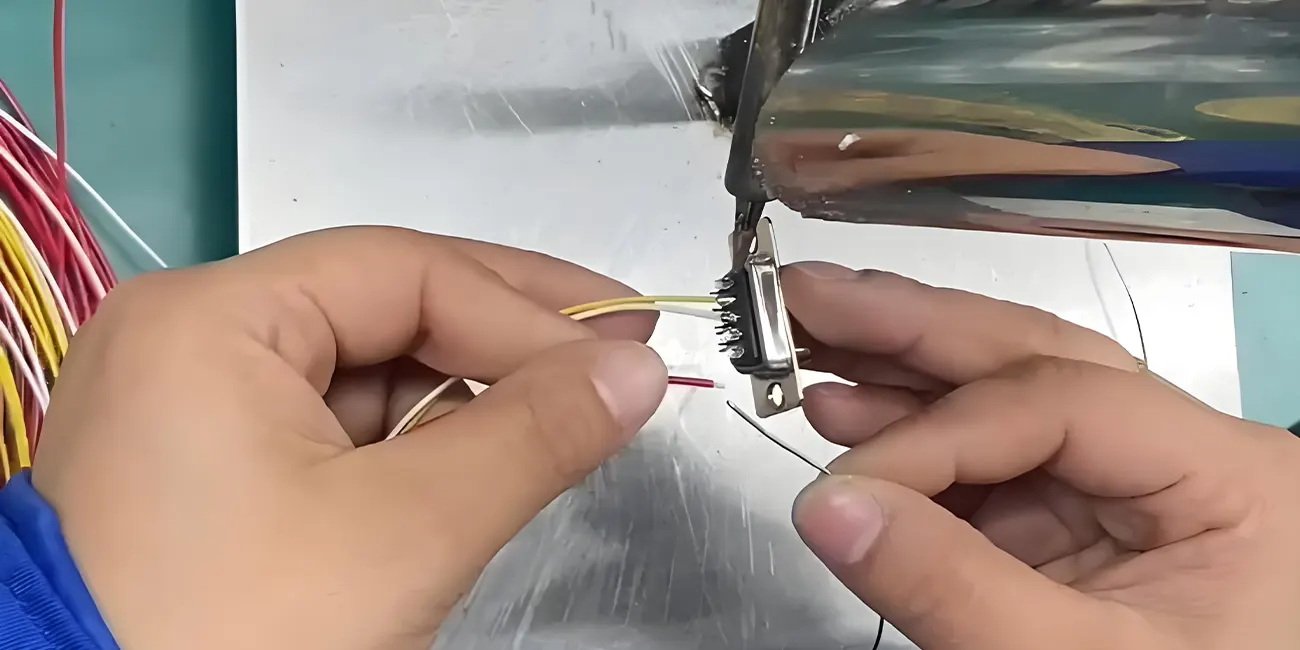
Wire harness soldering is an important joining method used to create electrical and mechanical connections between conductors and applicable terminals, contacts, splices, or other conductive interfaces. Consistent soldering performance helps maintain stable electrical continuity and reliable signal transmission for custom cable assemblies used in automotive, medical device, industrial automation, robotics, and renewable energy systems. Inconsistent workmanship and improper process control can lead to common soldering issues that cause intermittent signals, circuit irregularities, or premature component wear in end applications.
For design engineers, quality managers, and OEM procurement teams, understanding standard soldering workflows, typical joint defects, and practical control methods helps improve overall harness assembly reliability. This guide explains practical wire harness soldering principles, common workmanship defects, root causes, prevention practices, and industry-aligned quality control procedures.
1. What Is Wire Harness Soldering?
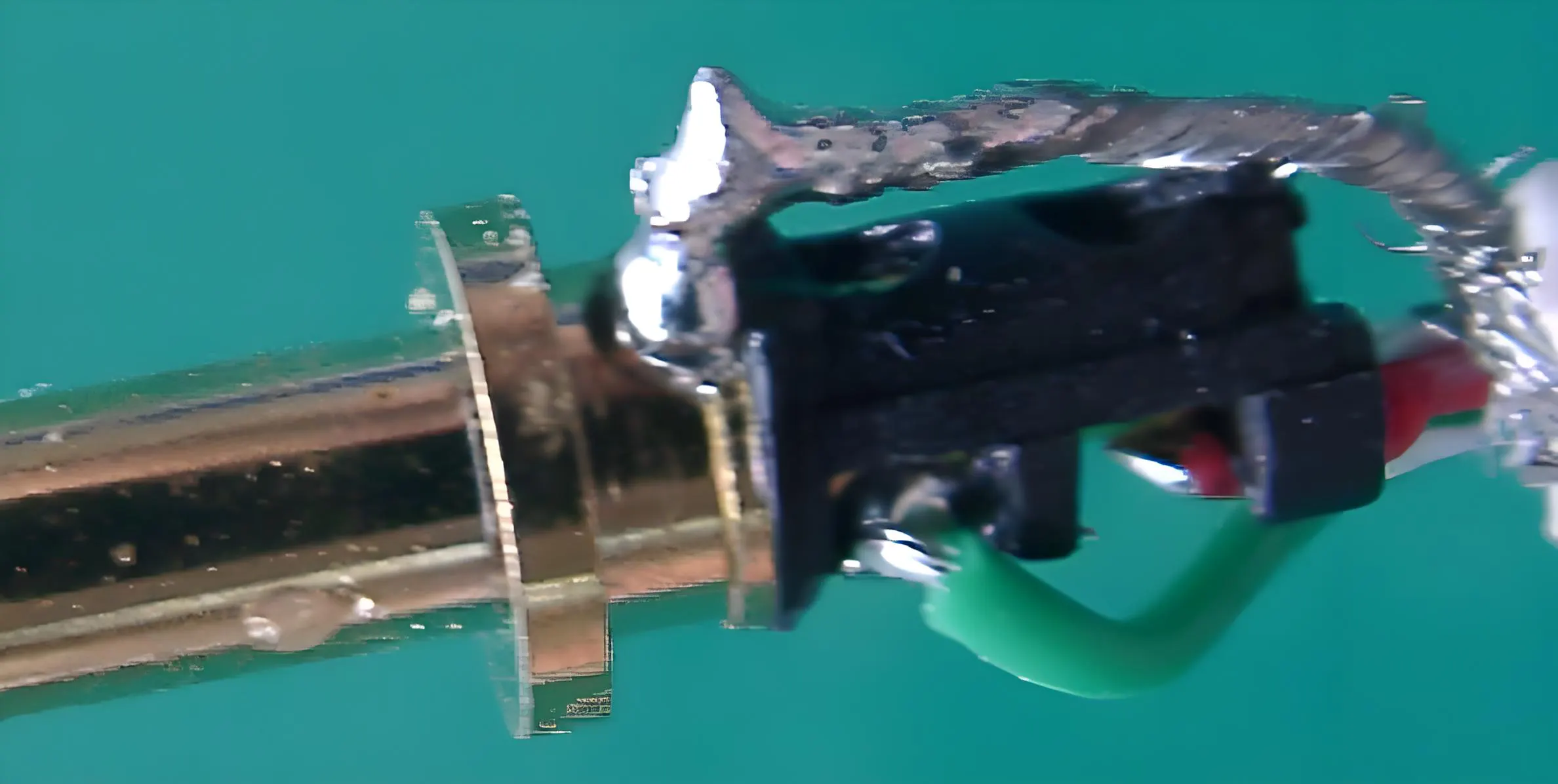
Wire harness soldering is a precision joining process that uses molten solder alloy to form durable electrical and mechanical connections between stripped wire conductors and various conductive interfaces, including connector terminals, solder cups, PCB pads, and wire splices.
Unlike welding, soldering joins materials primarily through a molten filler metal that wets and bonds to the surfaces being joined, without melting the base metals. Properly formed solder joints support stable electrical signal transmission and improved mechanical durability against routine vibration and temperature variation. As a key step in cable assembly manufacturing, consistent soldering workmanship directly impacts the service life and operational stability of finished wire harnesses.
2. Standard Wire Harness Soldering Process Overview
Mass production and prototype soldering for wire harnesses rely on repeatable, standardized workflows to reduce human error and sustain consistent joint quality. Wire harness assembly follows structured in-house procedures aligned with industry workmanship benchmarks across the following core steps:
Conductor Preparation: Precision wire stripping to avoid strand damage; thorough cleaning to remove dust, oil, and surface oxidation that limits solder wetting.
Flux Application: Controlled flux application to reduce oxidation, improve solder fluidity, and support uniform wetting between solder and conductor surfaces.
Precision Heating: Stable, even heating of conductors and contact surfaces to avoid insufficient heat transfer or localized overheating.
Solder Feeding and Wetting: Regulated solder volume to achieve complete, uniform coverage without excessive accumulation or insufficient filling.
Cooling and Solidification: Stationary cooling during solder solidification to prevent joint deformation and workmanship inconsistencies.
Post-Solder Inspection: Visual verification, mechanical sampling, and electrical testing to confirm joint usability for the intended application.
3. Common Wire Harness Soldering Defects: Causes, Risks and Prevention
The following are common soldering workmanship issues encountered in wire harness manufacturing. Each defect includes observable characteristics, typical root causes, field performance risks, and practical prevention measures.
3.1 Cold Solder Joint
Defect Description: A cold solder joint is a common soldering workmanship defect. The solder may appear to have formed a connection, but inadequate heating or wetting prevents the joint from developing the required bond and mechanical strength.
Common Causes: Insufficient soldering temperature, short heating duration, inconsistent heat transfer, surface contamination, or minor movement during solder solidification.
Potential Risks: Reduced mechanical tensile strength, increased susceptibility to loosening under vibration, intermittent signal fluctuation, and gradual performance degradation during long-term temperature cycling.
Prevention Methods: Maintain consistent process temperature parameters; ensure uniform heat penetration; clean all contact surfaces before soldering; secure wire positioning until solder fully solidifies.
3.2 Poor or Incomplete Solder Joint
Defect Description: A poor or incomplete solder joint may appear connected visually but does not provide the required electrical continuity or mechanical strength for reliable operation.
Common Causes: Inadequate solder wetting time, uneven heating, residual surface oxidation, and inconsistent solder melting behavior.
Potential Risks: Intermittent circuit performance, unstable signal transmission, and occasional connection dropout. Because visual appearance can be misleading, these defects often remain undetected until field deployment.
Prevention Methods: Standardize heating and melting durations; remove surface oxidation prior to assembly; apply appropriate flux to improve wetting; implement batch pull-force sampling for critical assemblies.
3.3 Excessive Solder Volume
Defect Description: Excess solder material creates oversized, uneven solder accumulations on terminals and splice joints.
Common Causes: Overfeeding solder, extended heating cycles, and inconsistent manual soldering technique.
Potential Risks: Solder bridging between adjacent pins or terminals, increased risk of short circuits, and physical interference during connector mating.
Prevention Methods: Regulate solder quantity during application; standardize heating duration; rework oversized joints to meet acceptable dimensional criteria.
3.4 Insufficient Solder Volume
Defect Description: Inadequate solder volume fails to fully cover the designated soldering zone, resulting in incomplete conductor wetting and exposed bonding gaps.
Common Causes: Limited solder feeding, surface contamination that reduces fluidity, and incomplete heating cycles.
Potential Risks: Reduced effective bonding area, weaker mechanical stability, and inconsistent electrical contact under vibration or current fluctuation.
Prevention Methods: Follow minimum solder volume requirements per process guidelines; optimize heating parameters for improved fluidity; clean contact surfaces to ensure consistent wetting.
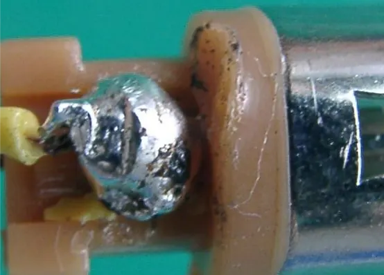
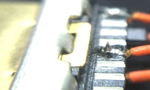
3.5 Solder Spike / Solder Icicle
Defect Description: Sharp, protruded solder formations appear on finished joint surfaces, resulting in non-conforming assembly geometry.
Common Causes: Improper soldering iron withdrawal angle, inconsistent withdrawal speed, and uneven solder solidification.
Potential Risks: Sharp solder burrs may damage insulating layers, creating leakage risks and reducing overall assembly yield.
Prevention Methods: Standardize tool handling and withdrawal motion; trim and rework defective spikes; enforce consistent workmanship criteria during visual inspection.
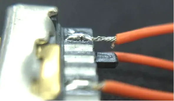
3.6 Inadequately Covered Conductors
Defect Description: Stripped conductor strands remain partially exposed within the designated soldering area due to incomplete solder coverage and wetting.
Common Causes: Misaligned wire positioning, insufficient solder volume, localized poor wetting, and offset soldering placement.
Potential Risks: Exposed strands are susceptible to oxidation and moisture ingress, which degrade conductivity over time. External friction and mechanical stress can also cause strand breakage and unstable contact.
Prevention Methods: Secure wire placement before soldering; verify full solder coverage of conductor strands; prioritize visual inspection for exposed wiring.
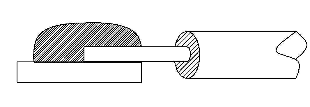
3.7 Conductor Retraction
Defect Description: Conductors retract backward from the intended soldering position, shortening the effective bonding length. According to Wire harness assembly applicable internal process specification, excessive retraction that leaves extended bare conductor is classified as non-conforming.
Common Causes: Temperature-induced thermal shift, inconsistent wire tension during processing, and unintended movement during solder cooling.
Potential Risks: Reduced bonding area lowers joint tensile strength, increasing the risk of conductor fracture in dynamic operating environments and compromising current and signal stability.
Prevention Methods: Maintain stable heating temperatures; control wire tension consistently during assembly; fix conductor positioning until solder fully solidifies.
4. Wire Harness Soldering Quality Control & Testing
Structured quality control minimizes process variation and identifies potential soldering defects before final shipment. Wire harness assembly implements layered inspection and testing workflows tailored to project specifications, customer requirements, and industry reference criteria.
Visual Inspection: All soldered joints undergo visual verification to check solder coverage, wetting uniformity, joint geometry, and absence of spikes, gaps, or exposed conductors.
Electrical Testing: Routine testing includes continuity verification and insulation resistance checks to confirm stable electrical performance and eliminate open or intermittent connection risks.
Mechanical Testing: Solder joint pull testing is performed on sampling or lot-basis to validate mechanical bonding strength, especially for vibration-critical applications.
Dimensional Verification: Inspections confirm conductor positioning, solder coverage range, and alignment meet internal process and customer drawing requirements.
Specialized Environmental Testing: Hipot (dielectric withstand) testing, salt spray testing, and mechanical vibration testing are applied when required by product specifications, application environment, or customer standards.
To identify and control potential soldering defects, applicable inspections and tests are selectively deployed according to project complexity and end-use requirements rather than applied universally to every unit.
5. Industry References & Custom Specification Alignment
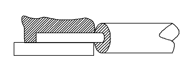
Wire harness assembly uses IPC/WHMA-A-620 as a workmanship and acceptance reference for applicable wire harness and cable assembly processes. Our applicable soldering workmanship requirements are developed with reference to IPC/WHMA-A-620 and customer-specific specifications, ensuring alignment with both industry baseline standards and project-level technical demands.
The facility maintains ISO 9001, IATF 16949, and ISO 13485 certifications, supporting structured process control for industrial, automotive, and medical-grade wire harness assemblies. All soldering workflows are documented, tracked, and traceable via the internal MES system to sustain consistent process performance across prototype and batch production.
6. Wire harness assembly Soldering & Cable Assembly Capabilities
Wire harness assembly provides custom wire harness soldering and cable assembly solutions covering prototype validation and full-scale production, with flexible MOQ options to support low-volume engineering samples and high-volume commercial orders. The in-house engineering team offers DFM review and process optimization based on customer drawings, BOM files, or physical samples to improve manufacturability and stabilize joint quality.
All finished assemblies undergo required electrical and visual inspections before shipment. Supported by an English-speaking project team and long-term global OEM experience, the company delivers application-specific wire harness solutions for automotive, medical, industrial automation, robotics, telecommunications, and renewable energy projects. Standard prototype turnaround ranges from 24 to 72 hours to accelerate customer product verification cycles.
7. Frequently Asked Questions
7.1 What standard governs wire harness soldering workmanship?
IPC/WHMA-A-620 serves as the primary industry reference for wire harness assembly workmanship, including soldering appearance, wetting quality, and general acceptance criteria. Manufacturers typically combine these baseline guidelines with customer-specific design and performance requirements.
7.2 What causes a cold solder joint in harness assembly?
Cold solder joints result from insufficient heat, short heating cycles, surface contamination, or movement during solder solidification. These factors prevent proper wetting and stable bond formation, leading to mechanically weak and electrically inconsistent connections.
7.3 How do you inspect soldered wire harness joints?
Soldered joints are verified through visual inspection, continuity and insulation testing, and periodic pull-force sampling. For high-reliability applications, additional hipot, vibration, or corrosion testing is performed per project requirements.
7.4 Why do soldered harness connections fail in long-term field use?
Most field failures stem from latent workmanship defects, including incomplete wetting, cold joints, solder irregularities, or conductor exposure. These minor inconsistencies degrade gradually under vibration, temperature cycling, and electrical load, eventually causing unstable connections.
7.5 Is soldering better than crimping for wire harnesses?
Neither method is universally better. The appropriate joining method depends on terminal design, conductor size, mechanical durability requirements, environmental conditions, production volume, and project specifications. Soldering excels for precise electrical continuity and fine-pitch connections, while crimping offers consistent mechanical strength for high-vibration mass-production applications.
8. Conclusion
Wire harness soldering performance depends on consistent process control, proper thermal management, and disciplined workmanship. Common soldering defects arise from inconsistent heating, surface contamination, misalignment, and unregulated solder volume, all of which can degrade assembly reliability in industrial, automotive, and medical applications. By referencing established industry standards and applying targeted inspection and testing workflows, manufacturers can stabilize soldering quality and reduce field failure risks. Structured process alignment and project-specific quality control remain the most reliable approach for consistent custom wire harness performance.